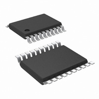
LM5118MH/NOPB National Semiconductor, LM5118MH/NOPB Datasheet - Page 11

LM5118MH/NOPB
Manufacturer Part Number
LM5118MH/NOPB
Description
IC CTLR BUCK-BOOST 20-TSSOP
Manufacturer
National Semiconductor
Series
PowerWise®r
Type
Step-Down (Buck), Step-Up (Boost)r
Datasheet
1.LM5118MHXNOPB.pdf
(26 pages)
Specifications of LM5118MH/NOPB
Internal Switch(s)
No
Synchronous Rectifier
Yes
Number Of Outputs
1
Voltage - Output
1.23 ~ 70 V
Frequency - Switching
500kHz
Voltage - Input
3 ~ 75 V
Operating Temperature
-40°C ~ 125°C
Mounting Type
Surface Mount
Package / Case
20-TSSOP Exposed Pad, 20-eTSSOP, 20-HTSSOP
Dc To Dc Converter Type
Step Up/Step Down
Pin Count
20
Input Voltage
3 to 75V
Output Voltage
1.23 to 70V
Output Current
3.5A
Package Type
TSSOP EP
Mounting
Surface Mount
Operating Temperature Classification
Automotive
Operating Temperature (min)
-40C
Operating Temperature (max)
125C
Package
20TSSOP EP
For Use With
LM5118EVAL - BOARD EVALUATION FOR LM5118
Lead Free Status / RoHS Status
Lead free / RoHS Compliant
Current - Output
-
Power - Output
-
Lead Free Status / Rohs Status
Compliant
Other names
LM5118MH
Available stocks
Company
Part Number
Manufacturer
Quantity
Price
Company:
Part Number:
LM5118MH/NOPB
Manufacturer:
ZARLINK
Quantity:
14
Operation Modes
Figure 4
mode and is useful for reference in the following discussions.
Initially, only the buck switch is active and the buck duty cycle
increases to maintain output regulation as VIN decreases.
When VIN is approximately equal to 15.5V, the boost switch
begins to operate with a low duty cycle. If VIN continues to
fall, the boost switch duty cycle increases and the buck switch
duty cycle decreases until they become equal at VIN = 13.2V.
Buck Mode Operation: VIN > VOUT
The LM5118 buck-boost regulator operates as a conventional
buck regulator with emulated current mode control while VIN
is greater than VOUT and the buck mode duty cycle is less
than 75%. In buck mode, the LO gate drive output to the boost
switch remains low.
illustrates how duty cycle affects the operational
FIGURE 4. Mode Dependence on Duty Cycle (VOUT =12V)
FIGURE 3. Buck-Boost Mode Operation
11
Buck-Boost Mode Operation: VIN
When VIN decreases relative to VOUT, the duty cycle of the
buck switch will increase to maintain regulation. Once the duty
cycle reaches 75%, the boost switch starts to operate with a
very small duty cycle. As VIN is further decreased, the boost
switch duty cycle increases until it is the same as the buck
switch. As VIN is further decreased below VOUT, the buck
and boost switch operate together with the same duty cycle
and the regulator is in full buck-boost mode. This feature al-
lows the regulator to transition smoothly from buck to buck-
boost mode. It should be noted that the regulator can be
designed to operate with VIN less than 4 volts, but VIN must
be at least 5 volts during start-up.
illustration of the gradual transition from buck to buck-boost
mode when the input voltage ramps downward over a few
switching cycles.
30058513
30058512
Figure 5
≊
VOUT
presents a timing
www.national.com


