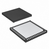
MAX8655ETN+T Maxim Integrated Products, MAX8655ETN+T Datasheet - Page 9

MAX8655ETN+T
Manufacturer Part Number
MAX8655ETN+T
Description
IC STEP-DN REG 25A 56-TQFN-EP
Manufacturer
Maxim Integrated Products
Type
Step-Down (Buck)r
Datasheet
1.MAX8655ETNT.pdf
(23 pages)
Specifications of MAX8655ETN+T
Internal Switch(s)
Yes
Synchronous Rectifier
No
Number Of Outputs
1
Voltage - Output
0.7 ~ 5.5 V
Current - Output
25A
Frequency - Switching
200kHz ~ 1MHz
Voltage - Input
4.5 ~ 25 V
Operating Temperature
-40°C ~ 85°C
Mounting Type
Surface Mount
Package / Case
56-TQFN Exposed Pad
Lead Free Status / RoHS Status
Lead free / RoHS Compliant
Power - Output
-
Lead Free Status / Rohs Status
Lead free / RoHS Compliant
PIN
40
41
43
44
45
46
47
50
—
—
—
GND-EP
PVIN-EP
SCOMP
SYNCO
FSYNC
NAME
MODE
LX-EP
ILIM2
POK
BST
LXB
_______________________________________________________________________________________
Internal MOSFET, Step-Down Regulator
Programmable Current-Limit Input. Connect a resistor from ILIM2 to GND to set the valley current
limit. See the Setting the Current Limit section.
Programmable Slope-Compensation Input. Internal slope-compensation voltage rate is the voltage at
SCOMP times 0.1 divided by the oscillator period (T). Connect SCOMP to AVL or GND to set to the
default of 250mV/T or 125mV/T, respectively.
Open-Drain Power-OK Output. POK goes high impedance when the output voltage rises above 91%
of the nominal regulation voltage. POK pulls low during shutdown or when the output drops below
88% of the nominal regulation voltage.
Frequency Set and Synchronization Input. Connect a resistor from FSYNC to GND to set the switching
frequency, or drive with a clock signal to synchronize between 160kHz and 1.2MHz. See the
Switching Frequency and Synchronization section.
Current-Limit Operating Mode Selection. Connect MODE to AVL for latch-off current limit or connect
MODE to GND for automatic recovery current limit.
Synchronization Output. Provides a clock output for synchronizing another MAX8655 with 180°
out-of-phase operation.
Boost Capacitor Connection. Connect a 0.22µF ceramic capacitor from BST to LXB.
LX Boost Capacitor Connection. Connect a 0.22µF ceramic capacitor between LXB and BST.
Exposed Pad. Connect to GND externally. See the Pin Configuration.
Exposed Pad. Internally connected to PVIN. See the Pin Configuration.
Exposed Pad. Internally connected to LX. See the Pin Configuration.
Highly Integrated, 25A, Wide-Input,
FUNCTION
Pin Description (continued)
9


