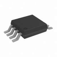
ADP1611ARMZ-R7 Analog Devices Inc, ADP1611ARMZ-R7 Datasheet

ADP1611ARMZ-R7
Specifications of ADP1611ARMZ-R7
Available stocks
Related parts for ADP1611ARMZ-R7
ADP1611ARMZ-R7 Summary of contents
Page 1
FEATURES Fully integrated 1 0.23 Ω power switch Pin-selectable 700 kHz or 1.2 MHz PWM frequency 90% efficiency Adjustable output voltage output regulation accuracy Adjustable soft start Input undervoltage lockout MSOP 8-lead package ...
Page 2
ADP1611 TABLE OF CONTENTS Specifications..................................................................................... 3 Absolute Maximum Ratings............................................................ 4 ESD Caution.................................................................................. 4 Pin Configuration and Function Descriptions............................. 5 Typical Performance Characteristics ............................................. 6 Theory of Operation ...................................................................... 10 Current-Mode PWM Operation .............................................. 10 Frequency Selection ................................................................... 10 Soft Start ...
Page 3
SPECIFICATIONS −40°C to +85°C, unless otherwise noted. All limits at temperature extremes are guaranteed by correlation and IN A characterization using standard statistical quality control (SQC), unless otherwise noted. Table 1. Parameter SUPPLY Input ...
Page 4
ADP1611 ABSOLUTE MAXIMUM RATINGS Table 2. Parameter IN, COMP, SD, SS, RT GND SW to GND RMS SW Pin Current Operating Ambient Temperature Range Operating Junction Temperature Range Storage Temperature Range θ , Two Layers JA θ , ...
Page 5
PIN CONFIGURATION AND FUNCTION DESCRIPTIONS Table 3. Pin Function Descriptions Pin No. Mnemonic Description 1 COMP Compensation Input. Connect a series resistor-capacitor network from COMP to GND to compensate the regulator Output Voltage Feedback Input. Connect a resistive ...
Page 6
ADP1611 TYPICAL PERFORMANCE CHARACTERISTICS 100 700kHz 10µ LOAD CURRENT (mA) Figure 4. Output Efficiency vs. Load Current 100 ...
Page 7
V = 10V OUT 0 2.5 3.0 3.5 4.0 4.5 SUPPLY VOLTAGE (V) Figure 10. Oscillatory Frequency vs. Supply Voltage 350 300 250 200 150 100 –40 – AMBIENT TEMPERATURE (°C) ...
Page 8
ADP1611 2 1.23kHz 1.8 1.6 1.4 1.2 1.0 0.8 0.6 –40 – AMBIENT TEMPERATURE (°C) Figure 16. Supply Current vs. Ambient Temperature 1 3. 0.4V ...
Page 9
OUT C OUT CH1 = I 200mA/DIV L = 10µH LOAD CH2 = V 200mV/DIV F OUT CH1 10.0mVΩ CH2 200mV M2.00µs A CH1 T 571.200µs Figure 22. Load Transient ...
Page 10
ADP1611 THEORY OF OPERATION The ADP1611 current-mode step-up switching converter converts a 2 5.5 V input voltage output voltage as high The 1.2 A internal switch allows a high output current, and ...
Page 11
Table 4. Inductor Manufacturers Vendor Part Sumida CMD4D11-2R2MC 847-956-0666 CMD4D11-4R7MC www.sumida.com CDRH4D28-100 CDRH5D18-220 CR43-4R7 CR43-100 Coilcraft 847-639-6400 DS1608-472 www.coilcraft.com DS1608-103 Toko 847-297-0070 D52LC-4R7M www.tokoam.com D52LC-100M Using the duty cycle and switching frequency, f the on time by the following equation: ...
Page 12
ADP1611 DIODE SELECTION The output rectifier conducts the inductor current to the output capacitor and load while the switch is off. For high efficiency, minimize the forward voltage drop of the diode. For this reason, Schottky rectifiers are recommended. However, ...
Page 13
For low ESR output capacitance, such as with a ceramic capaci- tor optional. For optimal transient performance, the R and C might need to be adjusted by observing the COMP COMP load transient response of the ADP1611. For ...
Page 14
ADP1611 APPLICATION CIRCUITS The circuit in Figure 27 shows the ADP1611 in a step-up configuration. The ADP1611 is used here to generate regulator with the following specifications 3 5 ...
Page 15
SEPIC POWER SUPPLY The circuit in Figure 30 shows the ADP1611 in a single-ended primary inductance converter (SEPIC) topology. This topology is useful for an unregulated input voltage, such as a battery- powered application in which the input voltage can ...
Page 16
ADP1611 LAYOUT PROCEDURE To achieve high efficiency, good regulation, and stability, a well- designed printed circuit board layout is required. Where possible, use the sample application board layout as a model. Follow these guidelines when designing printed circuit boards (see ...
Page 17
Figure 32. Sample Application Board (Top Layer) Figure 33. Sample Application Board (Silkscreen Layer) Rev Page ADP1611 ...
Page 18
... ADP1611 OUTLINE DIMENSIONS ORDERING GUIDE Model Temperature Range 1 ADP1611ARMZ-R7 −40°C to +85°C ADP1611-EVAL Pb-free part. 3.00 BSC 8 5 4.90 3.00 BSC BSC 4 PIN 1 0.65 BSC 1.10 MAX 0.15 0.00 8° 0.38 0.23 0° 0.22 0.08 COPLANARITY SEATING 0.10 PLANE COMPLIANT TO JEDEC STANDARDS MO-187AA Figure 34 ...
Page 19
NOTES Rev Page ADP1611 ...
Page 20
ADP1611 NOTES © 2005 Analog Devices, Inc. All rights reserved. Trademarks and registered trademarks are the property of their respective owners. D04906–0–2/05(0) Rev Page ...


