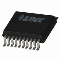
LICAL-DEC-MS001 Linx Technologies Inc, LICAL-DEC-MS001 Datasheet - Page 6

LICAL-DEC-MS001
Manufacturer Part Number
LICAL-DEC-MS001
Description
IC DECODER MS SERIES 20-SSOP
Manufacturer
Linx Technologies Inc
Series
MSr
Type
Decoderr
Datasheet
1.LICAL-DEC-MS001.pdf
(7 pages)
Specifications of LICAL-DEC-MS001
Package / Case
20-SSOP
Applications
RF, IR
Mounting Type
Surface Mount
Supply Voltage (max)
5.5 V
Supply Voltage (min)
2 V
Maximum Operating Temperature
+ 125 C
Minimum Operating Temperature
- 40 C
Mounting Style
SMD/SMT
Lead Free Status / RoHS Status
Lead free / RoHS Compliant
Lead Free Status / RoHS Status
Lead free / RoHS Compliant, Lead free / RoHS Compliant
Available stocks
Company
Part Number
Manufacturer
Quantity
Price
Company:
Part Number:
LICAL-DEC-MS001
Manufacturer:
Maxim
Quantity:
1 681
TYPICAL APPLICATIONS
Figure 6: MS Series Decoder Application Circuit
Page 10
The MS Series decoder is ideal for replicating button presses for remote control
applications. An example application circuit is shown below.
SPDT switches are used to select the baud rate and set the latch mode so that
pull-down resistors are not needed.
The RX_CNTL line can be connected to the PDN line of the receiver or it can be
connected directly to ground.
TX_ID can be connected to a microprocessor or a PC to record the transmitter
identity. Application Note AN-00156 has sample code that will read the
transmitter ID and display the ID number on a LCD screen.
A LED indicator is attached to the MODE_IND line to provide visual feedback to
the user that an operation is taking place. This line will source a maximum of
25mA, so the limiting resistor may not be needed, depending on the LED chosen
and the brightness desired.
The LEARN line is connected to a button that will pull the line high when pressed.
Since the line does not have an internal pull-down resistor, a 100kΩ resistor is
used to pull the line to ground when not in use.
The DATA_IN line is connected directly to the data output of the receiver.
Data Lines D0 through D7 can be connected directly to the external circuitry that
needs to be activated remotely. In this example, D5 is connected directly to a
piezoelectric buzzer. This will cause the buzzer to sound when the D5 line on the
encoder goes high. Line D6 will activate a relay through a transistor buffer when
it goes high. A buffer like this may be needed if the load requires more than
25mA of current or a higher voltage source to activate. The decoder will turn on
the transistor, which can be selected to provide the appropriate drive levels to
activate the relay.
To Processor or PC
To Receiver
10k
220
2.2k
10
1
2
3
4
5
6
7
8
9
D6
D7
SEL_BAUD0
SEL_BAUD1
GND
GND
LATCH
RX_CNTL
TX_ID
MODE
_IND
LICAL-DEC-MS001
DATA_IN
LEARN
VCC
VCC
D5
D4
D3
D2
D1
D0
20
19
18
17
16
15
14
13
12
11
100k
From Receiver
Figure 7: MS Series Decoder Flowchart
Clear All Memory
Pull MODE_IND
Pull MODE_IND
Line High For 2
Time-Out?
Line Low
10 Sec.
Sec.
YES
NO
NO
Flash MODE_IND
Save New Code
Pull MODE_IND
Pull RX_CNTL
Line 5 Times
Is Memory
Line Low
Line Low
Word
Full?
YES
YES
YES
YES
NO
Pull MODE_IND
Pull RX_CNTL
Start Toggling
Update Code
LEARN Line
LEARN Line
MODE_IND
RX_CNTL
Time-Out?
Valid Data
Received?
Line High
Line High
Was Any
17 Sec.
Used?
Learn
Mode
Is The
High?
Is The
High?
Word
Is
YES
YES
NO
NO
NO
NO
YES
Wait 9x "Time On"
(1 Packet + 10mS
Wait "Time On"
Pull RX_CNTL
Pull RX_CNTL
DATA_IN Line
LEARN Line
Transition?
Line High
Line Low
Did The
= 10%)
Is The
(90%)
High?
NO
YES
NO
YES
NO
Read Data Packet
Set Baud Rate
DATA_IN Line
DATA_IN Line
Output TX ID
LEARN Line
Output Data
Transition?
The Packet
First Loop?
Transition?
Time Out?
Power Up
RX_CNTL
Did The
Did The
Is The
Valid?
Used?
High?
Is
Is
YES
NO
NO
NO
YES
YES
YES
NO
NO
YES
Sleep
NO
YES
Go To
Learn
Mode
Page 11


