MCP2036T-I/MG Microchip Technology, MCP2036T-I/MG Datasheet - Page 10
MCP2036T-I/MG
Manufacturer Part Number
MCP2036T-I/MG
Description
INTEGRATED CIRCUITS LINEAR - 82
Manufacturer
Microchip Technology
Type
Sensor Interfacer
Datasheet
1.MCP2036-ISL.pdf
(30 pages)
Specifications of MCP2036T-I/MG
Applications
Analog I/O
Mounting Type
Surface Mount
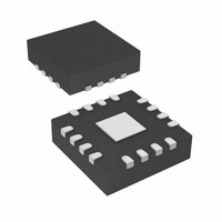
Package / Case
16-QFN
Lead Free Status / RoHS Status
Lead free / RoHS Compliant
Lead Free Status / RoHS Status
Lead free / RoHS Compliant, Lead free / RoHS Compliant
Available stocks
Company
Part Number
Manufacturer
Quantity
Price
Company:

Part Number:
MCP2036T-I/MG
Manufacturer:
MICROCHIP
Quantity:
12 000


MCP2036
The peak-to-peak amplitude of the resulting triangular
waveform, at the coil driver input, is shown in
Equation
EQUATION 3-5:
From the previous equation, the designer should
choose values for V
above, the value of C
EQUATION 3-6:
The amplitude of the pulsed current applied to key
inductors will be:
EQUATION 3-7:
This current produces a pulsed voltage to key inductors
ends. The amplitude of this voltage will be:
EQUATION 3-8:
DS22186B-page 10
C
IN
Note:
Note:
Note:
=
------------------------------------------------------------------ -
R
IN
ΔU
•
3-5:
V
ln
V
(600mV) for best performance.
Assuming a power supply of 5V and
V
have about 320pF. A 330pF capacitor will
be used.
For a PWM frequency of 2 MHz and
inductor value of 2.7µH, the amplitude of
pulsed voltage will be:
PKPK
⎛
⎜
⎝
=
V
--------------------------------------- -
V
L - Inductance of Key Inductor
PKPK
PKPK
F - PWM Frequency
G
DD
DD
L
DRV
t
•
ΔI
=
–
+
=500mV, for R
ΔI
----- -
Δt
V
V
should not exceed specified value
=
V
PKPK
PKPK
V
PKPK
=
ΔU
- Gain of Coil Driver
DD
IN
PKPK
V
PKPK
L V
will be:
=
•
⎞
⎟
⎠
•
=
------------------------------------------ -
1
and R
1
10.8mV
=
+
–
-------------------------------------------------------------------------------------
2 F R IN
PKPK
•
2ΔV
•
exp
exp
G
•
DRV
IN
IN
⎛
⎝
⎛
⎝
•
. Using the equation
----------------- -
R
----------------- -
R
=3.9KΩ, C
G
IN
IN
•
t –
t –
DRV
C
C
ln
IN
IN
⎛
⎜
⎝
1
--------------------------------------- -
V
V
•
⎞
⎠
⎞
⎠
DD
DD
2F
+
–
IN
V
V
should
PKPK
PKPK
⎞
⎟
⎠
The total voltage across both the reference and sensor
coils would be double (two series inductors). For a
specific power supply voltage, half of this power supply,
relative to the voltage reference, is available for output
amplifier/detector. Assuming a 30% margin, the
desired gain for the detector should be about:
EQUATION 3-9:
The gain of the amplifier is user-settable, using an
external resistor, R
be determined using the following equation:
EQUATION 3-10:
With a 10-bit ADC, using oversampling and averaging
techniques, the effective resolution is close to 11 bits.
As shown in AN1239, “Inductive Touch Sensor
Design”, the typical shift in sensor impedance is typi-
cally 3-4%, so the actual number of counts per press is
typically between 20 and 40 counts. In this way, the
microcontroller firmware could easily detect press
event.
Note:
For a power supply of 5V and ΔU = 10mV,
the resulted gain is 81. To obtain this gain,
R
GAIN
Gain R
Gain
= 820kOhm should be used.
GAIN.
=
∼
70%
---------------------------------
© 2009 Microchip Technology Inc.
The value of that resistor will
GAIN
2 ΔU
•
•
/10kOhm
⎛
⎝
V
---------- -
DD
2
⎞
⎠
Related parts for MCP2036T-I/MG
Image
Part Number
Description
Manufacturer
Datasheet
Request
R

Part Number:
Description:
IC KEYLESS ENTRY AFE 14-SOIC
Manufacturer:
Microchip Technology
Datasheet:

Part Number:
Description:
Capacitance Touch Sensors Inductive Sensor Ana Front End
Manufacturer:
Microchip Technology

Part Number:
Description:
Inductive Sensor Analog Front End Device
Manufacturer:
MICROCHIP [Microchip Technology]
Datasheet:
Part Number:
Description:
IC KEYLESS ENTRY AFE 14-SOIC
Manufacturer:
Microchip Technology
Datasheet:

Part Number:
Description:
IC KEYLESS ENTRY AFE 16-QFN
Manufacturer:
Microchip Technology
Datasheet:

Part Number:
Description:
IC KEYLESS ENTRY AFE 14-PDIP
Manufacturer:
Microchip Technology
Datasheet:
Part Number:
Description:
KEYLESS ENTRY AFE, IND SENSOR, 16QFN
Manufacturer:
Microchip Technology
Datasheet:
Part Number:
Description:
Inductive Sensor Analog Front End Device
Manufacturer:
Microchip Technology
Datasheet:

Part Number:
Description:
Manufacturer:
Microchip Technology Inc.
Datasheet:
Part Number:
Description:
Manufacturer:
Microchip Technology Inc.
Datasheet:
Part Number:
Description:
Manufacturer:
Microchip Technology Inc.
Datasheet:
Part Number:
Description:
Manufacturer:
Microchip Technology Inc.
Datasheet: