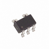
DS28CM00R-A00+T Maxim Integrated Products, DS28CM00R-A00+T Datasheet

DS28CM00R-A00+T
Specifications of DS28CM00R-A00+T
Available stocks
Related parts for DS28CM00R-A00+T
DS28CM00R-A00+T Summary of contents
Page 1
... Registration Number (8-bit Family Code + 48-bit Serial Number + 8-bit CRC) SMBus-Compatible I²C Serial Interface Supports 100kHz and 400kHz Communication Speeds 5V Tolerant Interface Pins Operating Range: 1.8V ±10 ±5%, -40°C to +85°C 5-Pin SOT23 Package ORDERING INFORMATION DS28CM00R-A00+T +Denotes lead-free package. PIN CONFIGURATION SDA SCL DS28CM00 ...
Page 2
ABSOLUTE MAXIMUM RATINGS Voltage Range on Any Pin Relative to Ground Maximum Current Into Any Pin Operating Temperature Range Junction Temperature Storage Temperature Range Soldering Temperature Stresses beyond those listed under “Absolute Maximum Ratings” may cause permanent damage to the ...
Page 3
PARAMETER Data Hold Time (Notes 9, 10) Data Setup Time Setup Time for STOP Condition Bus Free Time Between a STOP and START Condition Capacitive Load for Each Bus Line Note 1: Specifications at -40°C are guaranteed by design and ...
Page 4
Figure 1. Block Diagram SCL SDA Figure 2. Memory Map ADDRESS TYPE 00h ROM 01h ROM 02h ROM 03h ROM 04h ROM 05h ROM 06h ROM 07h ROM 08h SRAM Unique Registration Number Each DS28CM00 has a unique Registration Number ...
Page 5
DEVICE OPERATION Typically, the DS28CM00 is accessed after power-up to read the 64-bit Registration number, which may serve to identify the object that the device is embedded in. Write access exists only to the Control Register. Read and write access ...
Page 6
Figure 4. I²C/SMBus Protocol Overview MS-bit SDA Slave Address SCL 1 2 START Idle Condition Bus Idle or Not Busy Both, SDA and SCL, are inactive, i. e., in their logic HIGH states. START Condition To initiate communication with a ...
Page 7
Not Acknowledged by Slave A slave device may be unable to receive or transmit data, e.g., because it is busy SMBus-compatible device, the DS28CM00 will always acknowledge its slave address. However, some time later the slave may refuse ...
Page 8
I²C Communication⎯Legend SYMBOL DESCRIPTION S START Condition AD,0 Select DS28CM00 for Write Access AD,1 Select DS28CM00 for Read Access Sr Repeated START Condition P STOP Condition Command-Specific Communication⎯Color-Codes Master-to-Slave Slave-to-Master Communication Examples Write to Control Register (address 08) S AD,0 ...
Page 9
Figure 6. Application Schematic µC GND For I²C systems, the rise time and fall time are measured from 30% to 70% of the pullup voltage. The maximum bus capacitance C is 400pF. The maximum rise time must ...


