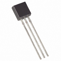
DS2401-SL+T&R Maxim Integrated Products, DS2401-SL+T&R Datasheet

DS2401-SL+T&R
Specifications of DS2401-SL+T&R
Related parts for DS2401-SL+T&R
DS2401-SL+T&R Summary of contents
Page 1
... FEATURES Upgrade and drop-in replacement for DS2400 — Extended 2.8 to 6.0 voltage range — Multiple DS2401s can reside on a ® common 1-Wire Net Unique, factory-lasered and tested 64-bit registration number (8-bit family code + 48- bit serial number + 8-bit CRC tester); guaranteed no two parts alike ...
Page 2
... The 1-Wire bus is a system which has a single bus master system and one or more slaves. In all instances, the DS2401 is a slave device. The bus master is typically a microcontroller. The discussion of this bus system is broken down into three topics: hardware configuration, transaction sequence, and 1-Wire signaling (signal type and timing) ...
Page 3
... DS2401 MEMORY MAP Figure 1 8-Bit CRC Code MSB LSB MSB DS2401 EQUIVALENT CIRCUIT Figure 2 BUS MASTER CIRCUIT Figure 3 Note: Depending on the 1-Wire communication speed and the bus load characteristics, the optimal pullup ) value will be in the 1.5k Ω Ω range. resistor (R ...
Page 4
... Presence Pulse(s) transmitted by the slave(s). The Presence Pulse lets the bus master know that the DS2401 is on the bus and is ready to operate. For more details, see the 1-Wire Signaling section. ROM FUNCTION COMMANDS Once the bus master has detected a presence, it can issue one of the four ROM function commands ...
Page 5
... DS2401. During write time slots, the delay circuit determines when the DS2401 will sample the data line. For a read data time slot “0” transmitted, the delay circuit determines how long the DS2401 will hold the data line low overriding the “1” generated by the master. ...
Page 6
ROM FUNCTIONS FLOW CHART Figure ...
Page 7
... INITIALIZATION PROCEDURE “RESET AND PRESENCE PULSES” Figure 5 RESISTOR MASTER DS2401 ∗ In order not to mask interrupt signaling by other devices on the 1-Wire bus less than 960 μ s. READ/WRITE TIMING DIAGRAM Figure 6 Write-One Time Slot RESISTOR MASTER 480 μ s ≤ t < ∞ * RSTL 480 μ ...
Page 8
... DS2401 CRC GENERATION To validate the data transmitted from the DS2401, the bus master may generate a CRC value from the data received. This generated value is compared to the value stored in the last 8 bits of the DS2401. If the two CRC values match, the transmission is error-free. ...
Page 9
ABSOLUTE MAXIMUM RATINGS* Voltage on any Pin Relative to Ground Operating Temperature Range Storage Temperature Range Soldering Temperature ∗ This is a stress rating only and functional operation of the device at these or any other conditions above those indicated ...
Page 10
NOTES: 1) All voltages are referenced to ground external pullup voltage. PUP 3) Input load is to ground additional reset or communication sequence cannot begin until the reset high time has expired. 5) Read data ...


