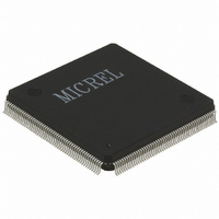
KS8999I Micrel Inc, KS8999I Datasheet - Page 15

KS8999I
Manufacturer Part Number
KS8999I
Description
IC SWITCH 9-PORT 10/100 208-PQFP
Manufacturer
Micrel Inc
Specifications of KS8999I
Applications
*
Mounting Type
Surface Mount
Package / Case
208-MQFP, 208-PQFP
Fiber Support
Yes
Integrated Led Drivers
Yes
Phy/transceiver Interface
MII/SNI
Power Supply Type
Analog/Digital
Package Type
PQFP
Data Rate (typ)
10/100Mbps
Vlan Support
Yes
Operating Temperature (max)
85C
Operating Temperature (min)
-40C
Mounting
Surface Mount
Jtag Support
No
Operating Temperature Classification
Industrial
Lead Free Status / RoHS Status
Contains lead / RoHS non-compliant
For Use With
576-1023 - BOARD EVAL EXPERIMENT FOR KS8999
Lead Free Status / RoHS Status
Not Compliant, Contains lead / RoHS non-compliant
Available stocks
Company
Part Number
Manufacturer
Quantity
Price
January 2005
Micrel, Inc.
Group
UP
MODESEL[3:0]
LED[1:9][2]
LED[1:9][3]
I/O Names
LED[1][3]
LED[1][2]
LED[1][1]
LED[1][0]
Active Status
H
L
L
Description
Output (after reset)
Mode 0: Collision (on = collision/off = no collision)
Mode 1: Transmit Activity (on during transmission)
Mode 2: Link activity (10Mb mode)
Mode 3: Full Duplex + Collision
(constant on = full duplex; intermittent on = collision; off = half-duplex with no
collision)
Output (after reset)
Mode 0: Link + Activity
When LED is solid “on”, it indicates the link is on for both 10 or 100BaseTX,
but no data is transmitting or receiving.
When LED is solid “off”, it indicates the link is off.
When LED is blinking, it indicates data is transmitting or receiving for either 10
or 100 BaseTX
Mode 1: Receive Activity (on = receiving/off = not receiving)
Mode 2: Link activity (100Mb mode)
Mode 3: Link + Activity (see description above)
Note: Mode is set by MODESEL[3:0] ; please see description in UP
(unmanaged programming) section.
Mode select at reset time. LED mode is selected by using the table below.
Note that under normal operation MODESEL[3:2] must be tied low.
MODESEL
3 2 1 0
0 0 0 0
0 0 0 1
0 0 1 0
0 0 1 1
0 1 0 0
0 1 0 1
0 1 1 0
0 1 1 1
1 0 0 0
1 0 0 1
1 0 1 0
1 0 1 1
1 1 0 0
1 1 0 1
1 1 1 0
1 1 1 1
Programs auto-negotiation on port 1
D = Disable auto-negotiation, F/U = Enable auto-negotiation (default)
Programs auto-negotiation on port 2
D = Disable auto-negotiation, F/U = Enable auto-negotiation (default)
Programs auto-negotiation on port 3
D = Disable auto-negotiation, F/U = Enable auto-negotiation (default)
Programs auto-negotiation on port 4 D = Disable auto-negotiation,
F/U = Enable auto-negotiation (default)
15
Mode select at reset time. LED mode is selected by using the
table below. Note that under normal operation
MODESEL[3:2] must be tied low.
Operation
LED mode 0
LED mode 1
LED mode 2
LED mode 3
Used for factory testing
Used for factory testing
Used for factory testing
Used for factory testing
Used for factory testing
Used for factory testing
Used for factory testing
Used for factory testing
Used for factory testing
Used for factory testing
Used for factory testing
Used for factory testing
KS8999
KS8999


