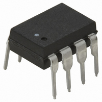
HCPL-2211-000E Avago Technologies US Inc., HCPL-2211-000E Datasheet - Page 10

HCPL-2211-000E
Manufacturer Part Number
HCPL-2211-000E
Description
OPTOCOUPLER LOGIC-OUT 5MBD 8DIP
Manufacturer
Avago Technologies US Inc.
Type
Logicr
Datasheet
1.HCPL-0201-500E.pdf
(18 pages)
Specifications of HCPL-2211-000E
Package / Case
8-DIP (0.300", 7.62mm)
Voltage - Isolation
5000Vrms
Number Of Channels
1, Unidirectional
Current - Output / Channel
25mA
Data Rate
5MBd
Propagation Delay High - Low @ If
150ns @ 3mA
Current - Dc Forward (if)
10mA
Input Type
DC
Output Type
Push-Pull, Totem-Pole
Mounting Type
Through Hole
Isolation Voltage
3750 Vrms
Maximum Continuous Output Current
25 mA
Maximum Fall Time
0.007 us
Maximum Forward Diode Current
10 mA
Output Device
Logic Gate Photo IC
Configuration
1 Channel
Maximum Baud Rate
5 MBd(Typ)
Maximum Forward Diode Voltage
1.7 V
Maximum Reverse Diode Voltage
5 V
Maximum Power Dissipation
210 mW
Maximum Operating Temperature
+ 85 C
Minimum Operating Temperature
- 40 C
Package Type
8-Pin DIP
No. Of Channels
1
Optocoupler Output Type
Logic Gate
Input Current
5mA
Output Voltage
20V
Opto Case Style
DIP
No. Of Pins
8
Common Mode Ratio
10k
Data Rate Max
5Mbps
Rohs Compliant
Yes
Lead Free Status / RoHS Status
Lead free / RoHS Compliant
Lead Free Status / RoHS Status
Lead free / RoHS Compliant, Lead free / RoHS Compliant
Other names
516-1537-5
Available stocks
Company
Part Number
Manufacturer
Quantity
Price
Company:
Part Number:
HCPL-2211-000E
Manufacturer:
AVAGO
Quantity:
5 000
Part Number:
HCPL-2211-000E
Manufacturer:
AVAGO/安华高
Quantity:
20 000
Recommended Operating Conditions
*The initial switching threshold is 1.6 mA or less. It is recommended that 2.2 mA be used to permit at least a 20% LED degradation guardband.
†The initial switching threshold is 1.8 mA or less. It is recommended that 2.5 mA be used to permit at least a 20% LED degradation guardband.
10
Absolute Maximum Ratings
Parameter
Power Supply Voltage
Forward Input Current (ON)
Forward Input Voltage (OFF)
Operating Temperature
Junction Temperature
Fan Out
Parameter
Storage Temperature
Operating Temperature
Average Forward Input Current
Peak Transient Input Current
Reverse Input Voltage
Average Output Current
Supply Voltage
Output Voltage
Total Package Power Dissipation
Output Power Dissipation
Lead Solder Temperature (Through Hole Parts Only)
Solder Reflow Temperature Profile
(Surface Mount Parts Only)
(≤ 1 µs Pulse Width, 300 pps)
(≤ 200 µs Pulse Width,
< 1% Duty Cycle)
HCPL-223X
HCNW22XX
HCNW22XX
HCPL-223X
HCNW22XX
Symbol
V
I
V
See Package Outline Drawings section
F(ON)
F(OFF)
T
T
N
Symbol
CC
I
260°C for 10 sec., up to seating plane
A
J
I
F(TRAN)
F(AVG)
V
P
T
T
V
V
P
I
CC
O
A
O
R
O
S
T
1.6 mm below seating plane
260°C for 10 sec.,
Min.
1.6*
1.8†
Min.
-0.5
-40
-40
-40
-55
4.5
0
-
See Figure 7
Max.
125
210
294
1.0
85
10
40
25
20
20
5
3
Max.
125
0.8
20
85
5
4
Units
mW
mA
mA
mA
°C
°C
A
V
V
V
TTL Loads
Units
mA
°C
°C
V
V
Note
1
1
1
1
1
2
1


