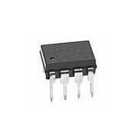
HCPL-3020-360E Avago Technologies US Inc., HCPL-3020-360E Datasheet - Page 13

HCPL-3020-360E
Manufacturer Part Number
HCPL-3020-360E
Description
OPTOCOUPLER 1CH 0.4A VDE 8SMD GW
Manufacturer
Avago Technologies US Inc.
Datasheet
1.HCPL-3020-500.pdf
(15 pages)
Specifications of HCPL-3020-360E
Voltage - Isolation
3750Vrms
Number Of Channels
1, Unidirectional
Current - Output / Channel
400mA
Propagation Delay High - Low @ If
200ns @ 7mA
Current - Dc Forward (if)
20mA
Input Type
DC
Output Type
Push-Pull, Totem-Pole
Mounting Type
Surface Mount, Gull Wing
Package / Case
8-SMD Gull Wing
No. Of Channels
1
Optocoupler Output Type
Gate Drive
Input Current
12mA
Output Voltage
30V
Opto Case Style
SMD
No. Of Pins
8
Propagation Delay Low-high
0.7µs
Isolation Voltage
3.75kV
Lead Free Status / RoHS Status
Lead free / RoHS Compliant
Available stocks
Company
Part Number
Manufacturer
Quantity
Price
Company:
Part Number:
HCPL-3020-360E
Manufacturer:
AVAGO
Quantity:
40 000
Part Number:
HCPL-3020-360E
Manufacturer:
AVAGO/安华高
Quantity:
20 000
LED Drive Circuit Considerations for Ultra High CMR
Performance
Without a detector shield, the dominant cause of optocou-
pler CMR failure is capacitive coupling from the input side
of the optocoupler, through the package, to the detector
IC as shown in Figure 19. The HCPL-3020 and HCPL-0302
improve CMR performance by using a detector IC with
an optically transparent Faraday shield, which diverts the
capacitively coupled current away from the sensitive IC
circuitry. However, this shield does not eliminate the ca-
pacitive coupling between the LED and optocoupler pins
5-8 as shown in Figure 20. This capacitive coupling causes
+5 V
Figure 19. Optocoupler input to output capacitance model for
unshielded optocouplers.
Figure 23. Recommended LED drive circuit for ultra-high CMR IPM
dead time and propagation delay specifications.
13
Figure 21. Equivalent circuit for figure 15 during common mode
1
2
3
4
+5 V
V
C
C
+
–
SAT
LEDN
LEDP
1
2
3
4
transient.
* THE ARROWS INDICATE THE DIRECTION
OF CURRENT FLOW DURING –dV
1
2
3
4
C
C
C
LEDP
LEDN
C
I
LEDP
LEDN
LEDP
SHIELD
SHIELD
V
+
CM
–
CM
/dt.
8
7
6
5
8
7
6
5
8
7
6
5
0.1
µF
+
–
Rg
V
CC
= 18 V
• • •
• • •
perturbations in the LED current during common mode
transients and becomes the major source of CMR failures
for a shielded optocoupler. The main design objective of
a high CMR LED drive circuit becomes keeping the LED in
the proper state (on or off ) during common mode tran-
sients. For example, the recommended application circuit
(Figure 17), can achieve 10 kV/µs CMR while minimizing
component complexity.
Techniques to keep the LED in the proper state are dis-
cussed in the next two sections.
Figure 22. Not recommended open collector drive circuit.
Figure 20. Optocoupler Input to output capacitance model for
shielded optocouplers.
1
2
3
4
+5 V
Q1
C
C
LEDN
LEDP
SHIELD
C
LEDO1
1
2
3
4
C
C
I
LEDN
LEDP
LEDN
C
SHIELD
LEDO2
8
7
6
5
8
7
6
5


