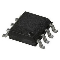
HCPL-7710-560E Avago Technologies US Inc., HCPL-7710-560E Datasheet - Page 16

HCPL-7710-560E
Manufacturer Part Number
HCPL-7710-560E
Description
OPTOCOUPLER 12MBD VDE 8-SMD
Manufacturer
Avago Technologies US Inc.
Datasheet
1.HCPL-7710-000E.pdf
(18 pages)
Specifications of HCPL-7710-560E
Voltage - Isolation
3750Vrms
Number Of Channels
1, Unidirectional
Current - Output / Channel
10mA
Data Rate
12.5MBd
Propagation Delay High - Low @ If
20ns
Input Type
Logic
Output Type
Push-Pull, Totem-Pole
Mounting Type
Surface Mount, Gull Wing
Package / Case
8-SMD Gull Wing
No. Of Channels
1
Optocoupler Output Type
Gate Drive
Input Current
10µA
Output Voltage
5V
Opto Case Style
SMD
No. Of Pins
8
Peak Reflow Compatible (260 C)
Yes
Isolation Voltage
3.75kV
Lead Free Status / RoHS Status
Lead free / RoHS Compliant
Available stocks
Company
Part Number
Manufacturer
Quantity
Price
Company:
Part Number:
HCPL-7710-560E
Manufacturer:
AVAGO
Quantity:
10 000
16
Power Supplies and Bypassing
The recommended DeviceNet application circuit is
shown in Figure 22. Since the HCPL-x710 are fully com-
patible with CMOS logic level signals, the optocoupler is
connected directly to the CAN transceiver. Two bypass
capacitors (with values between 0.01 and 0.1 µF) are
required and should be located as close as possible to
Figure 22. Recommended DeviceNet application circuit.
Implementing PROFIBUS with the HCPL-x710
An acronym for Process Fieldbus, PROFIBUS is essen-
tially a twisted-pair serial link very similar to RS-485
capable of achieving high-speed communication up to
12 MBd. As shown in Figure 23, a PROFIBUS Controller
(PBC) establishes the connection of a field automation
unit (control or central processing station) or a field
device to the transmission medium. The PBC consists
of the line transceiver, optical isolation, frame character
transmitter/receiver (UART), and the FDL/APP processor
with the interface to the PROFIBUS user.
0.01 µF
0.01 µF
TX0
RX0
ISO 5 V
ISO 5 V
GND
1
2
3
4
5
6
7
8
V
V
GND
GND
V
V
DD1
IN
O
DD2
BOUNDARY
HCPL-0710
HCPL-0710
ISOLATION
GALVANIC
1
2
GND
GND
V
V
DD2
DD1
V
V
IN
O
2
1
8
7
6
5
4
3
2
1
5 V
0.01
0.01
µF
µF
+
HCPL-0710 fig 21
0.01 µF
C4
TxD
Rs
the input and output power-supply pins of the HCPL-
x710. For each capacitor, the total lead length between
both ends of the capacitor and the power supply pins
should not exceed 20 mm. The bypass capacitors are
required because of the high-speed digital nature of the
signals inside the optocoupler.
MEDIUM
82C250
Figure 23. PROFIBUS Controller (PBC).
GND
V
5 V
CC
PBC
CANH
CANL
RXD
REF
(CENTRAL PROCESSING)
OPTICAL ISOLATION
CONTROL STATION
OR FIELD DEVICE
USER INTERFACE
PROFIBUS USER:
HCPL-0710 fig 22
+
TRANSCEIVER
PROCESSOR
FDL/APP
VREF
UART
REGULATOR
SWITCHING
LINEAR OR
30 V
D1
0.01 µF
500 V
C1
+
5 V+
4 CAN+
3 SHIELD
2 CAN–
1 V–
R1
1 M


