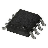
HCPL-7710#300 Avago Technologies US Inc., HCPL-7710#300 Datasheet - Page 15

HCPL-7710#300
Manufacturer Part Number
HCPL-7710#300
Description
OPTOCOUPLER CMOS 12MBD GW 8-SMD
Manufacturer
Avago Technologies US Inc.
Datasheet
1.HCPL-7710-000E.pdf
(18 pages)
Specifications of HCPL-7710#300
Voltage - Isolation
3750Vrms
Number Of Channels
1, Unidirectional
Current - Output / Channel
10mA
Data Rate
12.5MBd
Propagation Delay High - Low @ If
20ns
Input Type
Logic
Output Type
Push-Pull, Totem-Pole
Mounting Type
Surface Mount, Gull Wing
Package / Case
8-SMD Gull Wing
No. Of Channels
1
Isolation Voltage
3.75kV
Optocoupler Output Type
Gate Drive
Input Current
10µA
Output Voltage
5V
Opto Case Style
SMD
No. Of Pins
8
Propagation Delay Low-high
40ns
Common Mode Voltage Vcm
1000V
Lead Free Status / RoHS Status
Contains lead / RoHS non-compliant
Other names
516-1115-5
Available stocks
Company
Part Number
Manufacturer
Quantity
Price
15
Isolated Node Providing Power to the Network
Figure 21 shows a node providing power to the
network. The AC line powers a regulator which provides
five (5) volts locally. The AC line also powers a 24 volt
isolated supply, which powers the network, and another
five-volt regulator, which, in turn, powers the transceiv-
er and isolated (network) side of the two optocouplers.
This method is recommended when there are a limited
number of devices on the network that don’t require
much power, thus eliminating the need for separate
power supplies.
Figure 21. Isolated node providing power to the network.
DRAIN/SHIELD
SIGNAL
POWER
DEVICENET NODE
NODE/APP SPECIFIC
HCPL
0710
TRANSCEIVER
uP/CAN
HCPL
0710
HCPL-0710 fig 20
5 V REG.
5 V REG.
More importantly, the unique “dual-inverting” design
of the HCPL-x710 ensure the network will not “lock-up”
if either AC line power to the node is lost or the node
powered-off. Specifically, when input power (V
the HCPL-x710 located in the transmit path is eliminat-
ed, a RECESSIVE bus state is ensured as the HCPL-x710
output voltage (V
SWITCHING
ISOLATED
SUPPLY
POWER
AC LINE
O
) go HIGH.
V+ (SIGNAL)
V– (SIGNAL)
V+ (POWER)
V– (POWER)
GALVANIC
ISOLATION
BOUNDARY
DD1
) to


