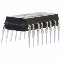
ILQ620 Vishay, ILQ620 Datasheet - Page 6

ILQ620
Manufacturer Part Number
ILQ620
Description
OPTOCPLR PHOTOTRAN 4CH 50% 16DIP
Manufacturer
Vishay
Specifications of ILQ620
Isolation Voltage
5300 Vrms
Number Of Channels
4
Input Type
AC, DC
Voltage - Isolation
5300Vrms
Current Transfer Ratio (min)
50% @ 5mA
Current Transfer Ratio (max)
600% @ 5mA
Voltage - Output
70V
Current - Output / Channel
50mA
Current - Dc Forward (if)
±60mA
Vce Saturation (max)
400mV
Output Type
Transistor
Mounting Type
Through Hole
Package / Case
16-DIP (0.300", 7.62mm)
Forward Current
60 mA
Maximum Input Diode Current
60 mA
Output Device
Transistor
Configuration
4
Maximum Collector Emitter Voltage
70 V
Maximum Collector Emitter Saturation Voltage
400 mV
Current Transfer Ratio
600 %
Maximum Forward Diode Voltage
1.3 V
Minimum Forward Diode Voltage
1 V
Maximum Collector Current
100 mA
Maximum Power Dissipation
500 mW
Maximum Operating Temperature
+ 100 C
Minimum Operating Temperature
- 55 C
No. Of Channels
4
Optocoupler Output Type
Phototransistor
Input Current
10mA
Output Voltage
70V
Opto Case Style
DIP
No. Of Pins
16
Input Current Max
10mA
Lead Free Status / RoHS Status
Lead free / RoHS Compliant
Lead Free Status / RoHS Status
Lead free / RoHS Compliant, Lead free / RoHS Compliant
Other names
751-1331-5
ILQ620GI
ILQ620GI
ILQ620GI
ILQ620GI
Available stocks
Company
Part Number
Manufacturer
Quantity
Price
ILD620/ 620GB / ILQ620/ 620GB
Vishay Semiconductors
www.vishay.com
6
iild620_09
iild620_10
Figure 10. Normalization Factor for Non-saturated and Saturated
iild620_11
Figure 11. Normalization Factor for Non-saturated and Saturated
100
Figure 9. Collector Current vs. Diode Forward Current
5.0
2.5
1.0
0.5
0.1
2.0
1.5
1.0
0.5
0.0
2.0
1.5
1.0
0.5
0.0
50
10
.1
.1
1
Normalized to:
V
CTRce(sat) V
Normalized to:
V
CTRce(sat) V
Normalized to
I
V
F
CE
CE
CE
= 10 mA
= 10 V, I
= 10 V, I
= 5 V
Forward Current - I
I F - LED Current - mA
I F - LED Current - mA
F
F
CE
1
CE
1
5
= 5 mA,
= 5 mA,
= 0.4 V
= 0.4 V
CTR vs. I
CTR vs. I
ILD/Q620
NCTRce
NCTRce
ILD/Q620GB
NCTRce(sat)
NCTRce(sat)
F
F
F
mA
10
10
10
T A = 50 °C
T A = 70 °C
100
100
20
iild620_12
iild620_13
iild620_14
Figure 12. Normalization Factor for Non-saturated and Saturated
10000
1000
100
200
150
100
2.0
1.5
1.0
0.5
0.0
Figure 13. Peak LED Current vs. Pulse Duration, Tau
50
10
0
-60
Figure 14. Maximum Detector Power Dissipation
10 -6 10 -5 10 -4 10 -3 10 -2 10 -1 10 0 10 1
.1
.005
Duty Factor
Normalized to:
V
CTRce(sat) V
.01
.02
.05
CE
.1
.2
.5
-40
= 10 V, I
t - LED Pulse Duration - s
Ta - Ambient Temperature - °C
-20
I F - LED Current - mA
F
CE
1
= 5 mA,
0
= 0.4 V
CTR vs. I
NCTRce
20
NCTRce(sat)
40
ˇ
F
10
Document Number 83653
60
t
DF = /t
T A = 100 °C
Rev. 1.4, 26-Oct-04
80
100
100


