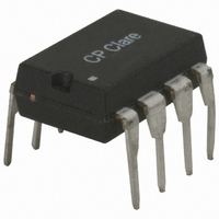
LOC111 Clare, LOC111 Datasheet - Page 2

LOC111
Manufacturer Part Number
LOC111
Description
OPTOCOUPLER TRANSISTOR 8-DIP
Manufacturer
Clare
Datasheet
1.LOC111PTR.pdf
(6 pages)
Specifications of LOC111
Number Of Channels
1
Input Type
DC
Voltage - Isolation
3750Vrms
Current Transfer Ratio (min)
0.73% @ 2mA ~ 10mA
Current Transfer Ratio (max)
1.07% @ 2mA ~ 10mA
Current - Dc Forward (if)
100mA
Output Type
Linear Phototransistor
Mounting Type
Through Hole
Package / Case
8-DIP
Lead Free Status / RoHS Status
Lead free / RoHS Compliant
Voltage - Output
-
Current - Output / Channel
-
Vce Saturation (max)
-
Other names
CLA116
Available stocks
Company
Part Number
Manufacturer
Quantity
Price
Company:
Part Number:
LOC111P-F
Manufacturer:
IXYS
Quantity:
12 400
Company:
Part Number:
LOC111P-G
Manufacturer:
IXYS
Quantity:
12 400
Part Number:
LOC111PTR
Manufacturer:
CLARE
Quantity:
20 000
Company:
Part Number:
LOC111PTR-F
Manufacturer:
BIVAR
Quantity:
5 600
Company:
Part Number:
LOC111PTR-G
Manufacturer:
IXYS
Quantity:
12 400
LOC111
Electrical Characteristics
2
Absolute Maximum Ratings (@ 25
Parameter
Coupler/Detector Characteristics @ 25°C
Input Characteristics @ 25°C
LED Voltage Drop
Reverse LED Current
Reverse LED Voltage
Forward LED Current
Dark Current
∆K3, Transfer Gain Linearity
K3 Temperature Coefficient
Common Mode
Total Harmonic Distortion
Frequency Response
Input/Output Capacitance
Input/Output Isolation
1
Parameter
Input Power Dissipation
Input Control Current
Total Package Dissipation
Isolation Voltage
Operational Temperature
Storage Temperature
Soldering Temperature
1
2
K1, Servo Gain (I
K2, Forward Gain (I
K3, Transfer Gain (K
(non-servoed)
Rejection Ratio
LOC111 and LOC112 Bins D,E,F,G.
Derate Linearly 1.33 mW/
Derate Linearly 6.67 mW/
Peak (10ms)
Input to Output
SOIC Package
(10 Seconds Max)
Flatpack Package
1
°
°
/I
C
C
2
F
2
/I
)
/K
F
)
1
)
1
1
3750
Min
-40
-40
-
-
-
-
-
-
Typ Max Units
Photoconductive Operation
-
-
-
-
-
-
-
-
Photovoltaic Operation
I
I
I
I
V=20V
F
F
F
F
o
=2-10mA, V
=2-10mA, V
=2-10mA, V
=2-10mA, V
I
F
+125
+260
+220
F
150
500
O
C)
100
+85
=0mA, V
Conditions
=350Hz, 0dBm
1
-
I
I
F
F
F=100Hz
1
2
=2-10mA
=2-10mA
V
P-P
R
V
=5V
-
-
, R
-
-
mW
mW
mA
°
°
°
°
RMS
A
C
C
C
C
CC
L
CC
CC
CC
=2KΩ,
det
www.clare.com
=15V
=15V
=15V
=15V
=-5V
BW (-3dB)
BW (-3dB)
Absolute Maximum Ratings are stress ratings. Stresses in
excess of these ratings can cause permanent damage to
the device. Functional operation of the device at these or
any other conditions beyond those indicated in the opera-
tional sections of this data sheet is not implied. Exposure
of the device to the absolute maximum ratings for an
extended period may degrade the device and effect its
reliability.
Symbol
∆K3/∆T
CMRR
∆K3
THD
C
V
V
K1
K2
K3
V
I
I
I
I/O
I/O
R
D
F
R
F
0.008
0.006
0.733
3750
Min
0.9
-96
-
-
-
-
-
-
-
-
-
-
0.005
Typ
130
200
-87
1.2
1.0
40
1
3
-
-
-
-
-
-
-
0.030
0.030
1.072
Max
100
1.4
1.0
-80
10
25
5
-
-
-
-
-
-
Units
%/
kHz
kHz
mA
V
µA
nA
dB
dB
pF
%
V
V
RMS
-
-
-
°
C
Rev. 6.0


