HCPL-181-00CE Avago Technologies US Inc., HCPL-181-00CE Datasheet
HCPL-181-00CE
Specifications of HCPL-181-00CE
HCPL-181-00CE
Available stocks


Related parts for HCPL-181-00CE


HCPL-181-00CE Summary of contents
Page 1
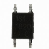
... RoHS 6 fully compliant options available; -xxxE denotes a lead-free product Description The HCPL-181 contains a light emitting diode optically coupled to a phototransistor packaged in a 4-pin mini-flat SMD package with a 2.0 mm profile. The small dimension of this product allows significant space saving. The package volume is 30% smaller than that of conven- tional DIP type ...
Page 2
... Ordering Information HCPL-181 is UL Recognized with 3750 Vrms for 1 minute per UL1577 and is approved under CSA Component Accep- tance Notice #5, File CA 88324 RoHS Compliant Option Rank '0' Rank 'A' Rank 'B' Part 50%<CTR 80%<CTR 130%<CTR Number <600% <160% <260% -000E -00AE -00BE HCPL-181 ...
Page 3
... Package Outline Drawings HCPL-181-000E 2.54 ± 0.25 181 D ATE C ODE 4.40 ± 0.2 LEAD FREE RANK DIMENSIONS IN MILLIMETERS. HCPL-181-060E 2.54 ± 0.25 181 V D ATE C ODE 4.40 ± 0.2 LEAD FREE RANK DIMENSIONS IN MILLIME TERS. Solder Reflow Temperature Profile 1. One-time soldering reflow is recommended within the condition of temperature and time profile shown at right ...
Page 4
... Max. Units Test Conditions 1 µ 250 KHz 100 – 0.1 mA – µ mA 600 % 0 mA µ 100 Ω 18 µ Ω – DC 500 60% R.H. 1 MHz 0 125 – FORWARD CURRENT – Figure 3. Collector-emitter saturation voltage vs. forward current. HCPL-181 fig 3 = 25˚ ...
Page 5
... T – AMBIENT TEMPERATURE – ° Figure 8. Collector-emitter saturation voltage HCPL-181 fig 8 vs. temperature kΩ kΩ 100 Ω 0 100 200 500 f – FREQUENCY – kHz Figure 11. Frequency response. HCPL-181 fig (MAX – COLLECTOR-EMITTER VOLTAGE – Figure 6. Collector current vs. collector-emitter voltage. HCPL-181 fig 6 ...
Page 6
Test Circuit for Response Time INPUT INPUT OUTPUT For product information and a complete list of distributors, please go to our web site: Avago, Avago Technologies, ...