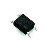
HCPL-354-000E Avago Technologies US Inc., HCPL-354-000E Datasheet - Page 5

HCPL-354-000E
Manufacturer Part Number
HCPL-354-000E
Description
OPTOCOUPLER PHOTO 2MM 4-MINIFLAT
Manufacturer
Avago Technologies US Inc.
Series
-r
Datasheet
1.HCPL-354-000E.pdf
(6 pages)
Specifications of HCPL-354-000E
Number Of Channels
1
Input Type
AC, DC
Voltage - Isolation
3750Vrms
Current Transfer Ratio (min)
20% @ 1mA
Current Transfer Ratio (max)
400% @ 1mA
Voltage - Output
35V
Current - Output / Channel
50mA
Current - Dc Forward (if)
±50mA
Vce Saturation (max)
200mV
Output Type
Transistor
Mounting Type
Surface Mount
Package / Case
4-Miniflat
No. Of Channels
1
Optocoupler Output Type
Phototransistor
Input Current
20mA
Output Voltage
35V
Opto Case Style
SOIC
No. Of Pins
4
Ctr Max
400%
Rise Time
4µs
Isolation Voltage
3.75kV
Breakdown Voltage
35V
Rohs Compliant
Yes
Lead Free Status / RoHS Status
Lead free / RoHS Compliant
Lead Free Status / RoHS Status
Lead free / RoHS Compliant, Lead free / RoHS Compliant
Available stocks
Company
Part Number
Manufacturer
Quantity
Price
Company:
Part Number:
HCPL-354-000E
Manufacturer:
TE
Quantity:
42 000
Figure 1. Forward current vs. ambient temperature.
Figure 4. Forward current vs. forward voltage.
Figure 7. Relative current transfer ratio vs. ambient
temperature.
5
500
200
100
150
100
60
50
40
30
20
10
50
20
10
50
0
5
2
1
0
-55
20
0
T
T
T
T
T
A
A
A
A
A
V
– AMBIENT TEMPERATURE – °C
– AMBIENT TEMPERATURE – °C
F
= 75°C
= 50°C
= 25°C
0
5
– FORWARD VOLTAGE – V
40
25
HCPL-354 fig 1
10
HCPL-354 fig 7
HCPL-354 fig 4
50
60
15
V
I
75
20
F
CE
= 1 mA
T
T
80
A
A
= 5 V
= 0°C
= -25°C
100
25
100
125
30
Figure 2. Collector power dissipation vs. ambient
temperature.
Figure 5. Current transfer ratio vs. forward current.
Figure 8. Collector-emitter saturation voltage vs.
ambient temperature.
200
150
100
140
120
100
50
80
60
40
20
0.10
0.08
0.06
0.04
0.02
0
0
-55
0.1
0
T
20
V
T
A
0.2
A
I
CE
F
T
– AMBIENT TEMPERATURE – °C
A
= 25°C
– FORWARD CURRENT – mA
0
= 5 V
I
– AMBIENT TEMPERATURE – °C
0.5
I
F
C
= 20 mA
= 1 mA
40
25
HCPL-354 fig 2
HCPL-354 fig 5
1
HCPL-354 fig 8
2
50
60
5
75
10
20
100
80
50
100
125
100
Figure 3. Collector-emitter saturation voltage vs.
forward current.
Figure 6. Collector current vs. collector-emitter volt-
age.
Figure 9. Collector dark current vs. ambient tempera-
ture.
10000
1000
50
40
30
20
10
V
100
0
CE
10
0
1
20
6
5
4
3
2
1
0
– COLLECTOR-EMITTER VOLTAGE – V
0
T
I
1
F
A
= 30 mA
V
I
– AMBIENT TEMPERATURE – °C
F
2
CE
2.5
– FORWARD CURRENT – mA
40
= 20 V
3
HCPL-354 fig 6
HCPL-354 fig 9
5.0
HCPL-354 fig 3
I
I
4
F
F
I
I
F
F
= 20 mA
= 10 mA
= 5 mA
= 1 mA
5
60
7.5
P
C
6
I
I
I
I
I
C
C
C
C
C
(MAX.)
= 0.5 mA
= 1 mA
= 3 mA
= 5 mA
= 7 mA
T
10.0
7
A
= 25°C
80
8
T
A
12.5
= 25°C
9
10
100
15.0


