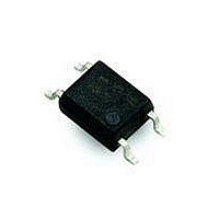
HCPL-354-06AE Avago Technologies US Inc., HCPL-354-06AE Datasheet - Page 4

HCPL-354-06AE
Manufacturer Part Number
HCPL-354-06AE
Description
OPTOCOUPLER PHOTO 2MM 4-MINIFLAT
Manufacturer
Avago Technologies US Inc.
Datasheet
1.HCPL-354-000E.pdf
(6 pages)
Specifications of HCPL-354-06AE
Number Of Channels
1
Input Type
AC, DC
Voltage - Isolation
3750Vrms
Current Transfer Ratio (min)
20% @ 1mA
Current Transfer Ratio (max)
400% @ 1mA
Voltage - Output
35V
Current - Output / Channel
50mA
Current - Dc Forward (if)
±50mA
Vce Saturation (max)
200mV
Output Type
Transistor
Mounting Type
Surface Mount
Package / Case
4-Miniflat
No. Of Channels
1
Optocoupler Output Type
Phototransistor
Input Current
20mA
Output Voltage
35V
Opto Case Style
SOIC
No. Of Pins
4
Ctr Max
150%
Isolation Voltage
3.75kV
Lead Free Status / RoHS Status
Lead free / RoHS Compliant
Available stocks
Company
Part Number
Manufacturer
Quantity
Price
Company:
Part Number:
HCPL-354-06AE
Manufacturer:
ON
Quantity:
1 000
Notes:
1. Isolation voltage shall be measured using the following method:
2.
4
Electrical Specifications (T
Absolute Maximum Ratings
Parameters
Storage Temperature
Ambient Operating Temperature
Lead Solder Temperature for 10s
(1.6 mm below seating plane)
Average Forward Current
Input Power Dissipation
Collector Current
Collector-Emitter Voltage
Emitter-Collector Voltage
Collector Power Dissipation
Total Power Dissipation
Isolation Voltage
(AC for 1 minute, R.H. = 40 ~ 60%)
Parameter
Forward Voltage
Terminal Capacitance
Collector Dark Current
Collector-Emitter Breakdown Voltage
Emitter-Collector Breakdown Voltage
Collector Current
Current Transfer Ratio
Collector-Emitter Saturation Voltage
Isolation Resistance
Floating Capacitance
Response Time (Rise)
Response Time (Fall)
Rank Mark
A
No Mark
(a) Short between anode and cathode on the primary side and between collector and emitter on the secondary side.
(b) The isolation voltage tester with zero-cross circuit shall be used.
(c) The waveform of applied voltage shall be a sine wave.
CTR =
I
I
C
F
x 100%
[2]
CTR (%)
50 ~ 150
20 ~ 400
A
[1]
= 25˚C)
Conditions
I
V
T
F
A
CE
Symbol
V
C
BV
BV
I
CTR
V
R
C
t
t
= ±1 mA,
I
= 25˚C
C
r
f
t
CEO
f
F
CE(sat)
iso
= 5 V,
CEO
ECO
Symbol
T
T
T
I
P
I
V
V
P
P
V
F
C
A
sol
S
I
CEO
ECO
C
tot
iso
Min.
–
–
–
35
6
0.2
20
–
5 x 10
–
–
–
10
Min.
–55
–55
Typ.
1.2
30
–
–
–
–
–
0.1
1 x 10
0.6
4
3
11
Max.
1.4
250
100
–
–
4
400
0.2
–
1
18
18
Max.
150
100
260
±50
70
50
35
6
150
170
3750
Units
V
pF
nA
V
V
mA
%
V
Ω
pF
µs
µs
Units
˚C
˚C
˚C
mA
mW
mA
V
V
mW
mW
V
rms
Test Conditions
I
V = 0, f = 1 kHz
V
I
I
I
V
I
DC 500 V
40 ~ 60% R.H.
V = 0, f = 1 MHz
V
R
F
C
E
F
F
CE
CE
CE
L
= ±20 mA
= 0.1 mA, I
= 10 µA, I
= ±1 mA,
= ±20 mA, I
= 100 Ω
= 20 V, I
= 5 V
= 2 V, I
C
F
F
= 2 mA,
= 0
F
= 0
C
= 0
= 1 mA


