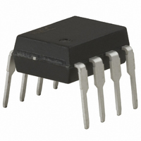
PS8601-A CEL, PS8601-A Datasheet - Page 6

PS8601-A
Manufacturer Part Number
PS8601-A
Description
PHOTOCOUPLR ANALOG HS OUT 8-D
Manufacturer
CEL
Series
NEPOCr
Datasheet
1.PS8601.pdf
(12 pages)
Specifications of PS8601-A
Number Of Channels
1
Input Type
DC
Voltage - Isolation
5000Vrms
Current Transfer Ratio (min)
15% @ 16mA
Voltage - Output
35V
Current - Output / Channel
8mA
Current - Dc Forward (if)
25mA
Output Type
Transistor with Vcc
Mounting Type
Through Hole
Package / Case
8-DIP
Isolation Voltage
5000 Vrms
Output Device
Integrated Photo IC
Current Transfer Ratio
15 %
Maximum Forward Diode Voltage
2.2 V
Maximum Reverse Diode Voltage
5 V
Maximum Input Diode Current
25 mA
Maximum Power Dissipation
100 mW
Maximum Operating Temperature
+ 100 C
Minimum Operating Temperature
- 55 C
Lead Free Status / RoHS Status
Lead free / RoHS Compliant
Vce Saturation (max)
-
Current Transfer Ratio (max)
-
Lead Free Status / RoHS Status
Lead free / RoHS Compliant, Lead free / RoHS Compliant
ELECTRICAL CHARACTERISTICS (T
USAGE CAUTIONS
6
Diode
Detector
Coupled
*1 Typical values at T
*2 Test circuit for propagation delay time
1. This product is weak for static electricity by designed with high-speed integrated circuit so protect against static
2. By-pass capacitor of more than 0.1
3. Avoid storage at a high temperature and high humidity.
(
electricity when handling.
distance between the leads of the photocoupler and capacitor is no more than 10 mm.
PW = 100 s
Duty Cycle = 1/10
Pulse Input
Forward Voltage
Reverse Current
Forward Voltage
Temperature Coefficent
Terminal Capacitance
High Level Output Current
High Level Output Current
Low Level Output Voltage
Low Level Supply Current
High Level Supply Current
DC Current Gain
Current Transfer Ratio
Isolation Resistance
Isolation Capacitance
Propagation Delay Time
(H → L)
Propagation Delay Time
(L → H)
I
F
Parameter
Monitor
µ
C
*2
*2
L
includes probe and stray wiring capacitance
)
A
= 25 °C
I
F
51 Ω
1
2
3
4
Symbol
∆
I
I
CTR
V
OH
OH
I
R
C
V
I
t
t
h
V
CCL
CCH
C
PHL
PLH
I
F
R
FE
OL
I-O
I-O
(1)
(2)
F
/
t
∆
T
µ
A
F is used between V
Data Sheet PN10262EJ01V0DS
8
7
6
5
= 25 °C)
I
V
I
V = 0 V, f = 1 MHz
I
I
I
I
I
V
I
V
V = 0 V, f = 1 MHz
I
I
F
F
F
F
F
F
F
F
F
F
R
O
I-O
= 16 mA
= 16 mA
= 0 mA, V
= 0 mA, V
= 16 mA, V
= 16 mA, V
= 0 mA, V
= 16 mA, V
= 16 mA, V
= 16 mA, V
= 5 V
= 5 V, I
= 1 kV
0.1
µ
F
O
DC
R
CC
CC
O
= 3 mA
C
V
CC
O
CC
CC
CC
L
= Open, V
Conditions
L
CC
= V
= V
= Open, V
= 15 pF
= 4.5 V, I
= 4.5 V, V
= 5 V, R
= 5 V, R
V
= 5 V
O
O
O
(Monitor)
= 5.5 V
= 35 V
CC
CC
L
L
O
CC
= 1.9 kΩ
= 1.9 kΩ
O
= 35 V
= 1.2 mA
and GND near device. Also, ensure that the
= 0.4 V
= 35 V
Input
Output
t
PHL
MIN.
10
15
11
t
PLH
TYP.
PS8601,PS8601L
−1.6
0.01
100
1.7
0.1
0.7
0.5
0.3
60
50
3
*1
MAX.
500
100
2.2
0.4
0.8
0.8
10
1
50 %
5 V
1.5 V
V
OL
mV/°C
Unit
µ
pF
nA
µ
µ
µ
pF
µ
µ
%
V
V
Ω
A
A
A
A
s
s


