KP-F1 Panduit Corp, KP-F1 Datasheet - Page 71
KP-F1
Manufacturer Part Number
KP-F1
Description
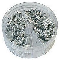
KIT FERRULE NONINS AWG22-14
Manufacturer
Panduit Corp
Series
Pan-Term®r
Type
Ferrule kitr
Datasheet
1.KP-FSD1.pdf
(1040 pages)
Specifications of KP-F1
Kit Type
Ferrule - Wire End
Values
370 pcs - Assorted Non-Insulated 22 ~ 14 AWG Ferrules
Kit Contents
500 Pieces Of F75-6, 400 Pieces Of F76-6 & F77-6, 300 Pieces Of F78-7, 200 Pieces Of F80-7
Lead Free Status / Rohs Status
Lead free / RoHS Compliant


Weather Resistant Nylon 6.6
Miniature Cross Section
Intermediate Cross Section
Standard Cross Section
Light-Heavy Cross Section
Heavy Cross Section
• Weather resistant material has greater resistance to damage
• Heat stabilized material for high temperature applications up to
• Designed to grip the bundle tightly to resist lateral movement of the
Heat Stabilized Nylon 6.6
Standard Cross Section
Light-Heavy Cross Section
Note: UL Listed and CSA Certified except SG450H-L0 and heat stabilized material (30).
Part Number
SG100M-C0
SG150I-C0
SG200S-C0
SG250S-C0
SG300S-C0
SG370S-C0
SG350LH-L0
SG450H-L0
SG200S-M30
SG300S-M30
SG350LH-TL30
caused by ultraviolet light – indoor or outdoor use
239°F (115°C) – indoor use
tie once installed
Super-Grip
10.4
12.4
15.3
15.3
18.6
12.4
15.3
4.2
6.2
8.3
8.3
In.
Length
mm
106
157
211
264
315
389
389
471
211
315
389
®
Cable Ties – Weather Resistant and Heat Stabilized Nylon 6.6
.118
.168
.225
.225
.225
.225
.330
.380
.225
.225
.330
In.
Width
For technical assistance in the U.S., call 866-405-6654 (outside the U.S., see inside back cover for directory)
mm
3.0
4.3
5.7
5.7
5.7
5.7
8.4
9.7
5.7
5.7
8.4
.038
.040
.046
.050
.050
.052
.064
.068
.046
.050
.064
Thickness
In.
ELECTRICAL SOLUTIONS
mm
1.0
1.0
1.2
1.3
1.3
1.3
1.6
1.7
1.2
1.3
1.6
1.50
2.00
2.60
3.20
4.20
4.13
5.20
2.00
3.20
4.13
.90
In.
• High strength allows the tie to withstand rough installation
• Thin, wide strap body provides flexibility enabling it to conform to
• Curved tip is easy to pick up from flat surfaces and allows faster
• Complementary mounts available, see pages B2.7, B2.11, B2.13
Bundle
practices that occur in MRO and construction environments
bundle while maintaining tensile strength
initial threading to speed installation
and B2.21
Max.
Dia.
mm
107
105
132
105
23
38
51
66
81
51
81
Lbs.
120
175
120
Min. Loop
18
40
50
75
75
75
50
70
Strength
Tensile
178
222
334
334
334
534
778
222
311
534
80
N
GTS, GTSL, GS2B,
GTS, GTSL, GS2B,
GTS, GTSL, GS2B,
GTS, GTSL, GS2B,
PTS, PPTS, STS2
PTS, PPTS, STS2
GTH, GS4H, PTS,
GTH, GS4H, PTS,
Recommended
STH2, ST3EH
STH2, ST3EH
GS4EH, PTH,
GS4EH, PTH,
GS4EH, PTH,
STH2, ST3EH
GTH, GS4H,
GTH, GS4H,
STS2, STH2
STS2, STH2
GTH, GS4H,
PTH, PPTS,
PTH, PPTS,
Installation
Tool
Pkg.
1000 10000
1000 10000
Std.
Qty.
100
100
100
100
100
100
250
50
50
1000
1000
1000
1000
1000
1000
2500
Std.
Ctn.
Qty.
500
500
B1.41
Management
Identification
Accessories
Connectors
Connectors
Grounding
Pre-Printed
& Write-On
Protection
Permanent
Solutions
Cable Ties
Terminals
Lockout/
Overview
Steel Ties
& Safety
Stainless
Raceway
Abrasion
Labeling
Systems
Surface
Markers
Tagout
System
Wiring
Labels
Power
Cable
Cable
Index
Duct
E5.
B1.
B2.
B3.
D1.
D2.
D3.
C1.
C2.
C3.
C4.
E1.
E2.
E3.
E4.
A.
F.