MD1170-D128-P SanDisk, MD1170-D128-P Datasheet - Page 10
MD1170-D128-P
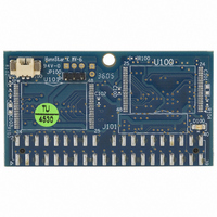
Manufacturer Part Number
MD1170-D128-P
Description
IDOC 128MB 40-IDE RIGHT
Manufacturer
SanDisk
Datasheet
1.MD1170-D64-P.pdf
(27 pages)
Specifications of MD1170-D128-P
Memory Size
128MB
Memory Type
FLASH - Nand
Lead Free Status / RoHS Status
Lead free / RoHS Compliant
Other names
585-1181


3.
3.1
Figure 1 shows iDiskOnChip operation from the system level, including the major hardware blocks.
iDiskOnChip integrates an IDE controller and flash devices. Communication with the host occurs
through the host interface, using the standard ATA protocol. Communication with the flash
device(s) occurs through the flash interface.
3.2
The controller is equipped with 16KB of internal memory that is used for storing code and data. The
internal memory can also be used as an intermediate memory for storing data blocks during a
wear-leveling procedure.
An 8KB internal boot ROM includes basic routines for accessing the flash memories and for
loading the main code into the internal memory
The host interface provides all required signals, is fully compliant with the PC Card standard, and
supports True-IDE mode operation requirements.
3.3
Highly sophisticated Error Correction Code algorithms are implemented. The ECC unit consists of
the Parity Unit (parity-byte generation) and the Syndrome Unit (syndrome-byte computation). This
unit implements a Reed-Solomon algorithm that can correct two bits per 512 bytes in an ECC block.
Code-byte generation during write operations, as well as error detection during read operation, is
implemented on the fly without any speed penalties.
9
Control & Address
T
Overview
Controller
Error Detection and Correction
Data Signals
HEORY OF
Signals
O
PERATION
Figure 1: iDiskOnChip Block Diagram
Bus Control
Decoder
Address
RAM
Data Sheet, Rev. 1.9
Controller
CPU
EDC/ECC
Control &
EPROM
Status
8-bit
8bit
Flash
Flash
iDiskOnChip (iDOC)
91-SR-012-01-8L
Related parts for MD1170-D128-P
Image
Part Number
Description
Manufacturer
Datasheet
Request
R

Part Number:
Description:
IDOC 64MB 40-IDE RIGHT
Manufacturer:
SanDisk
Datasheet:
Part Number:
Description:
IDOC 64MB 40-IDE RIGHT
Manufacturer:
SanDisk
Datasheet:
Part Number:
Description:
IDOC 32MB 40-IDE RIGHT
Manufacturer:
SanDisk
Datasheet:
Part Number:
Description:
IDOC 128MB 40-IDE RIGHT
Manufacturer:
SanDisk
Datasheet:
Part Number:
Description:
IDOC 16MB 40-IDE RIGHT
Manufacturer:
SanDisk
Datasheet:
Part Number:
Description:
IDOC 192MB 40-IDE RIGHT
Manufacturer:
SanDisk
Datasheet:
Part Number:
Description:
IDOC 256MB 40-IDE RIGHT
Manufacturer:
SanDisk
Datasheet:
Part Number:
Description:
IDOC 32MB 40-IDE RIGHT
Manufacturer:
SanDisk
Datasheet:
Part Number:
Description:
IDOC 512MB 40-IDE RIGHT
Manufacturer:
SanDisk
Datasheet:
