MD1160-D512 SanDisk, MD1160-D512 Datasheet - Page 7
MD1160-D512
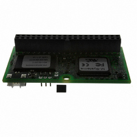
Manufacturer Part Number
MD1160-D512
Description
IDOC 512MB 40-IDE LEFT
Manufacturer
SanDisk
Datasheet
1.MD1160-D32.pdf
(23 pages)
Specifications of MD1160-D512
Memory Size
512MB
Memory Type
FLASH - Nand
Lead Free Status / RoHS Status
Contains lead / RoHS non-compliant
Other names
585-1058


2.3
Table 2 describes the pin descriptions for iDiskOnChip.
7
HD15-HD0
HA2-HA0
DIOW#
DIOR#
CSEL
CS0#
CS1#
RESET#
IORDY
INTRQ
IOIS16#
Signal
Pin Description
33,35,36
Pin No.
3-18
23
25
28
37
38
27
31
32
1
Host Data bus [15:0]. 16-bit bi-directional data input/output bus.
HD15 is the most significant bit, while HD0 is the least significant
bit. This bus carries data, commands and status information
between the host and iDiskOnChip. The lower 8 bits are used for
8-bit register transfers. Data transfers are 16 bits wide.
Host Address bus HA[2:0]: Select the registers in the iDiskOnChip
controller.
Device I/O Write: Active low. Gates the data from the bus to
iDiskOnChip. The clocking occurs on the rising edge of the signal.
Device I/O Read: Active low. Gates the data to the bus from
iDiskOnChip. The clocking occurs on the falling edge of the signal.
Configuration Select: Determines the device configuration as
either Master or Slave. If CSEL is negated, then the device
address is Master; if CSEL is asserted, then the device address is
Slave.
Host Chip Select 0: Active low. Selects the Command Block
registers.
Host Chip Select 1: Active low. Selects the Command Block
registers.
Host reset: Active low.
I/O Ready: Negated by iDiskOnChip to extend the host transfer
cycle (read or write) when the device is not ready to respond to a
data transfer request.
Interrupt Request: Interrupt request from iDiskOnChip to the host.
The output of this signal is tri-stated if the host disables the
interrupt. When asserted, this signal is negated by the device
within 400 nsec of the negation of the DIOR# signal that reads the
Status register. When asserted, this signal is negated by the
device within 400 nsec of the negation of the DIOW# signal that
writes the Command register.
I/O IS I6-Bit: Active low. Asserted (low) by iDiskOnChip to indicate
to the host that the current cycle is a 16-bit (word) data transfer.
When the signal is negated (high), an 8-bit data transfer is
performed.
Table 2: iDiskOnChip Pin Description
iDiskOnChip (iDOC) Data Sheet, Rev. 1.2
System Interface
Configuration
Control
Description
91-SR-012-01-8L
Signal
Output
Output
Output
Type
Input
Input
Input
Input
Input
Input
Input
I/O
Related parts for MD1160-D512
Image
Part Number
Description
Manufacturer
Datasheet
Request
R

Part Number:
Description:
IDOC 32MB 40-IDE LEFT
Manufacturer:
SanDisk
Datasheet:

Part Number:
Description:
IDOC 128MB 40-IDE LEFT
Manufacturer:
SanDisk
Datasheet:

Part Number:
Description:
IDOC 64MB 40-IDE LEFT
Manufacturer:
SanDisk
Datasheet:

Part Number:
Description:
IDOC 256MB 40-IDE LEFT
Manufacturer:
SanDisk
Datasheet:

Part Number:
Description:
IDOC 256MB 40-IDE LEFT
Manufacturer:
SanDisk
Datasheet:

Part Number:
Description:
IDOC 32MB 40-IDE LEFT
Manufacturer:
SanDisk
Datasheet:

Part Number:
Description:
IDOC 128MB 40-IDE LEFT
Manufacturer:
SanDisk
Datasheet:
Part Number:
Description:
IDOC 16MB 40-IDE LEFT
Manufacturer:
SanDisk
Datasheet:
Part Number:
Description:
IDOC 192MB 40-IDE LEFT
Manufacturer:
SanDisk
Datasheet: