INTMUSB3FT Matrix Orbital, INTMUSB3FT Datasheet
INTMUSB3FT
Specifications of INTMUSB3FT


Related parts for INTMUSB3FT


INTMUSB3FT Summary of contents
Page 1
Technical Manual Revision1.1 PCB Revision: 1.0 or greater Firmware Revision: 1.0 or greater ...
Page 2
Revision 1.0 1.1 0.1 0.2 0.3 0.4 Internal Smaller Magazine Text Reformat 0.5 Internal Re-organization and Connections Addition 0.6 0.7 Minor Changes in preparation of Release 0.8 Command Reformat and Minor Image Fixes (Initial Release) Revision History Description Initial Release ...
Page 3
... USB Connectors.....................................................................................................................................................................................12 Power/Communication Header.............................................................................................................................................................12 AC Power Input.....................................................................................................................................................................................13 Protocol Select......................................................................................................................................................................................13 Keypad..................................................................................................................................................................................................14 General Purpose Output.......................................................................................................................................................................14 Dallas One-Wire....................................................................................................................................................................................15 Manual Override...................................................................................................................................................................................15 Troubleshooting........................................................................................................................................................................16 Power....................................................................................................................................................................................................16 Display...................................................................................................................................................................................................16 Communication.....................................................................................................................................................................................16 Manual Override...................................................................................................................................................................................16 Commands ................................................................................................................................................................................17 Appendix....................................................................................................................................................................................34 Character Set.........................................................................................................................................................................................34 Environmental.......................................................................................................................................................................................35 Electrical................................................................................................................................................................................................35 Optical...................................................................................................................................................................................................35 Dimensional Drawing............................................................................................................................................................................36 Ordering....................................................................................................................................................................................37 Options..................................................................................................................................................................................................37 Accessories............................................................................................................................................................................................38 Production Products..................................................................................................................................................................41 Display Options.....................................................................................................................................................................................41 Definitions.................................................................................................................................................................................43 Contact Info...............................................................................................................................................................................44 1 ...
Page 4
... The following pages will outline these features in greater detail and provide instruction for connecting and communicating to the Matrix Orbital DevDevil. Using just the information provided and a little imagination, the DevDevil can open the door to a world of exciting display possibilities! 2 ...
Page 5
Quick Start Parts Included *Note: If any parts are missing from your order, please contact a sales associate as quickly as possible using the Contact Information at the end of ...
Page 6
Basic Connections 1 USB Connector 2 Serial DB9 Connector 3 Power/Communication Header 4 AC Power Input Illustration 2: DevDevil Basic Connections 5 Protocol Select Switches 6 Input Select Jumper 7 Voltage Select Jumper Table 2: DevDevil Basic Connections 4 ...
Page 7
USB Cables Required EXTMUSB3FT Illustration 3: USB Connection The USB connection is the quickest, easiest solution for PC development. After driver installation, the DevDevil will be accessible through a virtual serial port, providing the same result as a serial setup ...
Page 8
Serial Cables Required ACPC, CSS4FT Illustration 4: RS232 Connection Serial protocol provides a classic alternative the the USB method listed above. Two additional cables are required for this connection; the 4 ft serial cable and AC power adapter. These must ...
Page 9
... Illustration 2: DevDevil Basic Connections.. 4. Create. i. This time you're on your own. While there are many examples within the Matrix Orbital AppNote section, www.matrixorbital.ca/appnotes, in development, it's a breeze to switch over to another protocol, and fellow developers are always on our forums, http://www ...
Page 10
... Commands can be sent to an attached display by issuing decimal commands using the number pad. While the ALT key is held down, four digit decimal values can be sent as a single ASCII character. For example, to clear the screen try the following sequence. Any commands or text desired can be sent to the communication port using this method to provide total control of any Matrix Orbital display ...
Page 11
... The Matrix Orbital alphanumeric display tuner, or uProject, is offered as a free download from the support site. It allows the basic functionality of any While basic functionality can be tested using the GUI portion of the program, more advanced users will enjoy the scripting capability found in the uploader tab. Here commands can be stacked, run, and saved for later use. Although many commands are available to be dragged into the script dialog, perhaps the most powerful is the raw data command found in the other branch ...
Page 12
Hardware Advanced Connections 8 Screen* 9 Power Indicator 10 Optional Power Through DB9 11 Serial Communication Indicators 12 Optional Alternate USB 13 USB Communication Indicators 14 Keypad Header *Note: The 4x20 LCD screen shown, the DevDevil is also available with ...
Page 13
Screen The DevDevil provides a twenty character column alphanumeric display that is either two or four rows high. Both of these popular screens are available in an array of colours on a variety of Production modules listed in the appendix ...
Page 14
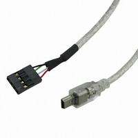
... USB Connectors Mating Cables EXTMUSB3FT, INTMUSB3FT Illustration 9: Mini and Alternate USB Connections with Indicators The mini USB configuration is supplied for communication and power input. To order the DevDevil with the alternate USB header populated for more advanced applications, contact a Matrix Orbital sales representative. In order to power the DevDevil using USB, ensure that the Voltage Select jumper is removed and the Power Select jumper is set to USB ...
Page 15
AC Power Input Mating Cables ACPC In addition to the methods mentioned above, the DevDevil can be powered with adapter. The output voltage of any device must be between 9 and 15 volts DC and the ...
Page 16
... Mating Cables KPP4X4 Facilitating user input, the keypad interface header allows a Matrix Orbital or any other passive matrix style input device to be attached to the DevDevil in a 5x5 row, column format. A customizable value is returned to the host each time one of the five row pins is connected to a column pin. Two additional pins are offered on either side of these inputs to provide a single ground and a selectable ground or power pin to provide grounding or backlight capabilities to an external input device ...
Page 17
... Only non-parasitic devices, those drawing power from the dedicated pin rather than the data line, have been tested, however, the data line has been pulled high through the nearby resistor to facilitate parasitic operation. A simple temperature monitoring application has been provided using the Matrix Orbital probe. Manual Override A Manual Override feature is available on the DevDevil to override all settings to their factory defaults ...
Page 18
... Ensure the contrast is not too high or too low. This can result in a darkened or blank screen respectively. See ● manual override below. Make sure that the start screen is not blank possible to overwrite the Matrix Orbital logo start screen, if this ● happens the screen may be blank. Try writing to the display to ensure it is functional, after checking the contrast above ...
Page 19
Commands 1. Communications 1.1.Changing the I2C Dec Slave Address Hex ASCII Immediately changes the write address. Address 1 byte, even value 1.2.Changing the Dec 254 57 Baud Rate Hex ASCII Immediately changes the baud rate. Can be ...
Page 20
Text 2.1.Control Characters* 8 Backspace 10 (08Hex) (0AHex) *Note: Regular text can be sent using regular alphanumeric strings or individual character values, starting at 65. 2.2.Auto Scroll Dec 254 81 On Hex FE 51 ■ ASCII Entire contents of ...
Page 21
Auto Line Dec 254 67 Wrap On Hex FE 43 ASCII Text will wrap to the next consecutive line once a row becomes full. Display default is auto line wrap on. 2.7.Set Auto Line Dec 254 68 Wrap Off ...
Page 22
Dec 254 74 Cursor On Hex FE 4A ■ ASCII Displays a line under the current cursor position. Can be used with block cursor. 2.13.Underline Dec 254 75 Cursor Off Hex FE 4B ■ ASCII Removes line under current ...
Page 23
Special Characters 3.1.Create a Custom Dec Character Hex ASCII Creates a custom character. Each character is divided into 8 rows of 5 pixels, each data byte represents one row. Each byte is padded by three zero bits followed by ...
Page 24
Custom Dec Characters Hex Loads a bank of custom characters into memory for use. Must be issued before using a bank of characters. Alternatively, an appropriate initialize command can be used. Bank 1 byte, memory bank ID (0-4) 3.4.Save ...
Page 25
Large Dec Numbers* Hex ASCII Loads the large number custom character bank into memory. Large numbers must be initialized before use. 3.8.Place Large Dec 254 35 Number* Hex FE 23 ASCII Places a single large decimal digit of 4 ...
Page 26
Dec 254 118 Vertical Bar Hex FE 76 ASCII Loads the horizontal bar graph custom character bank into memory. Horizontal bar characters must be initialized before a graph is displayed. 3.12.Place Dec 254 61 Vertical Bar Hex FE 3D ...
Page 27
General Purpose Output 4.1.General Purpose Dec Output Off Hex ASCII Turns the specified GPO off. Will only affect onboard LEDs if LED enable is jumped. Number 1 byte, GPO (1- turned off 4.2.General Purpose Dec Output On ...
Page 28
Dallas 1-Wire 5.1.Search for a Dec 254 200 2 1-Wire Device Hex Sends a search query to all of the devices on the one wire bus. Any connected device will respond with a identification packet. Response ...
Page 29
Dec 254 200 1 Transaction Hex Preforms a single Dallas 1-Wire transaction. Consult your device documentation for information regarding device specific protocols error is encountered, a corresponding value will be returned by the ...
Page 30
Keypad 6.1.Auto Transmit Dec 254 65 Key Presses On Hex ASCII Key presses are automatically sent to the host when received by the display. Default is auto transmit on. 6.2.Auto Transmit Dec Key Presses Off Hex ASCII Key presses ...
Page 31
Auto Dec 254 126 Repeat Mode Hex Sets key press repeat mode to typematic or hold. In typematic mode if a key press is held, the key value is transmitted immediately, then 5 times a second after a 1 ...
Page 32
Display Functions 7.1.Display On Dec 254 66 Hex FE 42 ■ ASCII Turns the display backlight on for a specified length of time inverse display color is used this command will essentially turn on the text. Minutes ...
Page 33
Dec 254 153 Brightness* Hex FE 99 Immediately sets the backlight brightness inverse display color is used this represents the text brightness instead. Default is 255. Brightness 1 byte, brightness level from 0(Dim)-255(Bright) 7.6.Set and Save Dec ...
Page 34
Data Security 8.1.Set Dec 254 147 Remember Hex FE 93 Allows changes to specific settings to be saved to the display memory. Writing to memory can be slow and each change consumes 1 write of approximately 100,000 available. Set ...
Page 35
Miscellaneous 9.1.Read Version Dec 254 54 Number Hex FE 36 ASCII Causes display to respond with it's firmware version number. Response 1 byte, convert to hexadecimal to view major and minor revision numbers 9.2.Read Module Dec 254 55 Type ...
Page 36
Appendix Character Sets Illustration 17: DevDevil LCD Series Character Table 34 ...
Page 37
Illustration 18: DevDevil VFD Series Character Table 35 ...
Page 38
Environmental Operating Temperature Storage Temperature Operating Relative Humidity Electrical Current Consumption Board 50mA Backlight Consumption 10. 20x2 20x4 Optical Screen Size Viewing Area Active Area Character Size Character Pitch Pixel Size Pixel Pitch Viewing Angle Luminance Backlight Half-Life *Note: A ...
Page 39
Dimensional Drawing Illustration 19: DevDevil Dimensional Drawing 37 ...
Page 40
Ordering Options # Designator 1 Product Line 2 Product Type 3 Display Type 4 Display Size 5 Screen Size 6 Color *Note: Available on 20x2 display models only **Note: Available on 20x4 display models only DD -DB1 -AL 202 C ...
Page 41
... Accessories Power ACPC* PC5V PC12V PCUSB *Note: Recommended Optional Accessory AC Power Converter 5V Power Cable 12V Power Cable USB Power Cable Table 17: DevDevil Power Accessories 39 ...
Page 42
... Communication CSS1FT CSS4FT** EXTMUSB3FT* INTMUSB3FT SCCPC5V BBC** *Note: Included Accessory **Note: Recommended Optional Accessory 1 ft. Serial Cable 4 ft. Serial Cable Mini-USB Cable Internal Mini-USB Cable Serial Communication/5V Power Cable Breadboard Cable Table 18: DevDevil Communication Accessories 40 ...
Page 43
... Peripherals KPP4X4 Temperature Probe 16 Button Keypad Dallas One-Wire Temperature Probe Table 19: DevDevil Peripheral Accessories 41 ...
Page 44
Production Products Display Options Protocol* LK/VK202-25 LK/VK202-25-USB LK/VK204-45 LK/VK204-25-USB USB Not Available RS232 TTL I2C Input Voltage 5V (Regular) 9-15V (-V) 9-35V (-VPT) Connectors DB9 Serial Mini-USB** Power/Data AC Power PC Power*** *Note: Protocol is selected using zero ohm jumper ...
Page 45
Peripherals LK/VK202-25 LK'VK202-25-USB LK/VK204-45 LK/VK204-25-USB Keypad* GPO** DOW*** *Note: Only the 1x12 keypad header is available on production units, a keypad such as the KPP4X4 unit must be purchased to interface with the display. **Note: Only the 2x7 GPO header ...
Page 46
... C: Inter-integrated circuit protocol employing a clock and data line to communicate a short distance at slow speeds between a master and up to 128 addressable slave devices. A Matrix Orbital display is a slave device. LCD: Liquid crystal display. LSB: Least significant bit or byte in a transmission, the rightmost when read. ...
Page 47
Contact Info Sales Phone: 403.229.2737 Email: sales@matrixorbital.ca Support Phone: 403.204.3750 Email: support@matrixorbital.ca Online Purchasing: www.matrixorbital.com Support: www.matrixorbital.ca 45 ...