HCMS-2913 Avago Technologies US Inc., HCMS-2913 Datasheet - Page 6
HCMS-2913
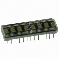
Manufacturer Part Number
HCMS-2913
Description
LED DISPLAY 5X7 8CHAR 3.8MM GRN
Manufacturer
Avago Technologies US Inc.
Series
HCMS-29xxr
Datasheet
1.HCMS-2903.pdf
(16 pages)
Specifications of HCMS-2913
Display Type
Alphanumeric
Common Pin
*
Millicandela Rating
*
Size / Dimension
1.40" L x 0.40" W x 0.20" H (35.6mm x 10.2mm x 5.1mm)
Color
Green
Configuration
5 x 7
Voltage - Forward (vf) Typ
*
Package / Case
26-DIP
Number Of Digits/alpha
8
Digit/alpha Size
0.15" (3.8mm)
Number Of Digits
8
Character Size
2.11 mm x 3.71 mm
Illumination Color
Green
Wavelength
574 nm
Operating Voltage
5 V
Operating Current
10 mA
Maximum Operating Temperature
+ 85 C
Minimum Operating Temperature
- 40 C
Luminous Intensity
114 ucd
Power Consumption
2.4 W
Viewing Area (w X H)
33.26 mm x 3.71 mm
Lead Free Status / RoHS Status
Lead free / RoHS Compliant
Lead Free Status / RoHS Status
Lead free / RoHS Compliant, Lead free / RoHS Compliant
Other names
516-1176-5


Optical Characteristics at 25°C
V
Display Color
AlGaAs Red
High Efficiency Red
Orange
Yellow
Green
Notes:
1. Refers to the initial case temperature of the device immediately prior to measurement.
2. Measured with all LEDs illuminated.
3. Dominant wavelength, l
Electrical Description
Pin Function
RESET (RST)
DATA IN (D
DATA OUT (D
CLOCK (CLK)
REGISTER SELECT (RS)
CHIP ENABLE (CE)
OSCILLATOR SELECT (SEL)
OSCILLATOR (OSC)
BLANK (BL)
GND
GND
V
V
6
LED
LED
LOGIC
LED color.
= 5.0 V, 50% Peak Current, 100% Pulse Width
LED
LOGIC
IN
)
OUT
)
d
, is derived from the CIE chromaticity diagram and represents the single wavelength which defines the perceived
[1]
Part Number
HCMS-29X5
HCMS-29X2
HCMS-29X4
HCMS-29X1
HCMS-29X3
Description
Sets Control Register bits to logic low. The Dot Register contents are unaffected by
the Reset pin. (logic low = reset; logic high = normal operation).
Serial Data input for Dot or Control Register data. Data is entered on the rising edge
of the Clock input.
Serial Data output for Dot or Control Register data. This pin is used for cascading
multiple displays.
Clock input for writing Dot or Control Register data. When Chip Enable is logic low,
data is entered on the rising Clock edge.
Selects Dot Register (RS = logic low) or Control Register (RS = logic high) as the des-
tination for serial data entry. The logic level of RS is latched on the falling edge of the
Chip Enable input.
This input must be a logic low to write data to the display. When CE returns to logic
high and CLK is logic low, data is latched to either the LED output drivers or a Control
Register.
Selects either an internal or external display oscillator source. (logic low = External
Display Oscillator; logic high = Internal Display Oscillator).
Output for the Internal Display Oscillator (SEL = logic high) or input for an External
Display Oscillator (SEL = logic low).
Blanks the display when logic high. May be modulated for brightness control.
Ground for LED drivers.
Ground for logic.
Positive supply for LED drivers.
Positive supply for logic.
Luminous Intensity per LED
Character Average (µcd)
Min.
95
29
29
29
57
Typ.
230
64
64
64
114
[2]
Peak
Wavelength
l
Typ.
645
635
600
583
568
Peak
(nm)
Dominant
Wavelength
l
Typ.
637
626
602
585
574
d [3]
(nm)
Related parts for HCMS-2913
Image
Part Number
Description
Manufacturer
Datasheet
Request
R

Part Number:
Description:
LED DISPLAY 5X7 4CHAR 5MM GREEN
Manufacturer:
Avago Technologies US Inc.
Datasheet:

Part Number:
Description:
LED DISPLAY 5X7 8CHAR 3.8MM YLW
Manufacturer:
Avago Technologies US Inc.
Datasheet:

Part Number:
Description:
LED DISPLAY 5X7 4CHAR 3.8MM YLW
Manufacturer:
Avago Technologies US Inc.
Datasheet:

Part Number:
Description:
LED DISPLAY 5X7 4CHAR 3.8MM ORN
Manufacturer:
Avago Technologies US Inc.
Datasheet:

Part Number:
Description:
LED DISPL 5X7 4CHAR 3.8MM ALGAAS
Manufacturer:
Avago Technologies US Inc.
Datasheet:
Part Number:
Description:
LED DISPLAY 5X7 4CHAR 3.8MM RED
Manufacturer:
Avago Technologies US Inc.
Datasheet:
Part Number:
Description:
LED DISPLAY 5X7 4CHAR 3.8MM ORN
Manufacturer:
Avago Technologies US Inc.
Datasheet:
Part Number:
Description:
LED DISPLAY 5X7 4CHAR 3.8MM YLW
Manufacturer:
Avago Technologies US Inc.
Datasheet:
Part Number:
Description:
LED DISPLAY 5X7 4CHAR 5MM YLW
Manufacturer:
Avago Technologies US Inc.
Datasheet:
Part Number:
Description:
LED DISPLAY 5X7 4CHAR 5MM ORN
Manufacturer:
Avago Technologies US Inc.
Datasheet:
Part Number:
Description:
LED DISPLAY 5X7 4CHAR 5MM GRN
Manufacturer:
Avago Technologies US Inc.
Datasheet:
Part Number:
Description:
LED DISPLAY 5X7 4CHAR 5MM RED
Manufacturer:
Avago Technologies US Inc.
Datasheet:
Part Number:
Description:
LED DISPLAY 5X7 4CHAR 3.8MM RED
Manufacturer:
Avago Technologies US Inc.
Datasheet:
Part Number:
Description:
LED DISPLAY 5X7 4CHAR 3.8MM GRN
Manufacturer:
Avago Technologies US Inc.
Datasheet:
Part Number:
Description:
LED DISPLAY 5X7 4CHAR 5MM GRN
Manufacturer:
Avago Technologies US Inc.
Datasheet: