SCF5740 OSRAM Opto Semiconductors Inc, SCF5740 Datasheet - Page 10
SCF5740
Manufacturer Part Number
SCF5740
Description
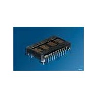
DISPLAY 4CHAR .270" 5X7 RED
Manufacturer
OSRAM Opto Semiconductors Inc
Series
Intelligent Display®r
Datasheet
1.SCF5740.pdf
(15 pages)
Specifications of SCF5740
Millicandela Rating
55µcd
Size / Dimension
1.30" L x 0.79" W x 0.28" H (33.02mm x 20.07mm x 7mm)
Color
Red
Configuration
5 x 7
Number Of Digits
4
Character Size
0.27 in
Illumination Color
Red
Wavelength
650 nm
Maximum Operating Temperature
+ 85 C
Minimum Operating Temperature
- 40 C
Luminous Intensity
55 ucd
Viewing Area (w X H)
4.45 mm x 6.86 mm
Display Type
5 x 7 Dot Matrix
Lead Free Status / RoHS Status
Lead free / RoHS Compliant
Voltage - Forward (vf) Typ
-
Internal Connection
-
Lead Free Status / Rohs Status
Details
Other names
Q68000A8848


Row Strobing
The SCF574X allows a high frequency external oscillator source
to drive the display. Data bit, D4, in the control word format con-
trols the prescaler function. The prescaler allows the oscillator
source to be divided by 16 by setting D4=1. However, the pres-
caler should not be used, i.e., when using the internal oscillator
source.
The Software Clear (C0
(page 10), clears the Address Register and the RAM. The display
is blanked and the Character Address Register will be set to Char-
acter 0. The internal counter and the Control Word Register are
unaffected. The Software Clear will remain active until the next
data input cycle is initiated.
Software Clear
Op code
D7 D6
1
Multiplexer and Display Driver
The four characters are row multiplexed with RAM resident column
data. The strobe rate is established by the internal or external
MUX Clock rate. The MUX Clock frequency is divided by a 448
counter chain. This results in a typical strobe rate of 768 Hz. By
pulling the Clock SEL line low, the display can be operated from an
external MUX Clock. The external clock is attached to the CLK I/O
connection (pin 9). The maximum external MUX Clock frequency
should be limited to 1.0 MHz.
An asynchronous hardware Reset is also provided. Bringing this
pin low will clear the Character Address Register, Control Word
Register, RAM, and blanks the display. This action leaves the dis-
play set at Character Address 0, and the Brightness Level set at
100%.
2006-01-23
1
Control Word
D5 D4
0
0
Row
Load
D3
0
HEX
0
1
2
3
4
5
6
Load Row 0
0
), given in Table „Software Clear“
Columns
D2
0
1 2 3 4
D1
0
0
1
2
3
4
5
6
D0
0
Load Row 1
0 1 2 3 4
Columns
Hex
C0
0
1
2
3
4
5
6
Operation
Level
CLEAR
Load Row 2
0 1 2 3 4
Columns
0
1
2
3
4
5
6
Load Row 3
0 1 2 3 4
10
Columns
Electrical & Mechanical Considerations
Thermal Considerations
Optimum product performance can be had when the following
electrical and mechanical recommendations are adopted. The
SCF574X’s IC is constructed in a high speed CMOS process, con-
sequently high speed noise on the SERIAL DATA, SERIAL DATA
CLOCK, LOAD and RESET lines may cause incorrect data to be
written into the serial shift register. Adhere to transmission line ter-
mination procedures when using fast line drivers and long cables
(< 10 cm).
When the internal MUX Clock is being used connect the CLKSEL
pin to V
nected to the system’s reset control, it is recommended that this
pin be connected to the center node of a series 0.1 µF and 100 kΩ
RC network. Thus upon initial power up the RESET will be held
low for 10 ms allowing adequate time for the system power supply
to stabilize.
ESD Protection
The input protection structure of the SCF574X provides significant
protection against ESD damage. It is capable of withstanding dis-
charges greater than 2.0 kV. Take all the standard precautions,
normal for CMOS components. These include properly grounding
personnel, tools, tables, and transport carriers that come in contact
with unshielded parts. If these conditions are not, or cannot be
met, keep the leads of the device shorted together or the parts in
anti-static packaging.
Soldering Considerations
The SCF574X can be hand soldered with SN63 solder using a
grounded iron set to 260°C.
Wave soldering is also possible following these conditions: Pre-
heat that does not exceed 93°C on the solder side of the PC board
or a package surface temperature of 85°C. Water soluble organic
acid flux (except carboxylic acid) or rosin-based RMA flux without
alcohol can be used.
Wave temperature of 245°C ± 5°C with a dwell between 1.5 sec. to
3.0 sec. Exposure to the wave should not exceed temperatures
above 260°C for five seconds at 1.59 mm (0.063") below the seat-
ing plane. The packages should not be immersed in the wave.
CC
0
1
2
3
4
5
6
Load Row 4
0
. In those applications where RESET will not be con-
Columns
1 2 3 4
SCF5740, SCF5742, SCF5744
0
1
2
3
4
5
6
Load Row 5
0 1
Columns
2 3 4
0
1
2
3
4
5
6
Load Row 6
0 1 2 3 4
Columns
IDXX5190
Related parts for SCF5740
Image
Part Number
Description
Manufacturer
Datasheet
Request
R

Part Number:
Description:
INTELLIGENT DISP 4CHAR 5X7 HERED
Manufacturer:
OSRAM Opto Semiconductors Inc
Datasheet:

Part Number:
Description:
DISPLAY 8DIGIT CERAMIC GREEN
Manufacturer:
OSRAM Opto Semiconductors Inc
Datasheet:

Part Number:
Description:
EMITTER IR 950NM 5MM SMD RADIAL
Manufacturer:
OSRAM Opto Semiconductors Inc
Datasheet:

Part Number:
Description:
LED TOPLED GREEN 570NM 2-PLCC
Manufacturer:
OSRAM Opto Semiconductors Inc
Datasheet:

Part Number:
Description:
INTERRUPTER RELFECT W/FILTR SMD
Manufacturer:
OSRAM Opto Semiconductors Inc
Datasheet:

Part Number:
Description:
LED Displays 5x7 Green 0.145 , 4-CHARACTER
Manufacturer:
OSRAM Opto Semiconductors Inc
Datasheet:

Part Number:
Description:
Q65110A4321_SIDELED PURE GREEN EOL150407
Manufacturer:
OSRAM Opto Semiconductors Inc
Datasheet:
Part Number:
Description:
Q65110A1202_RO DETECTOR 3/5MM_TR_RO
Manufacturer:
OSRAM Opto Semiconductors Inc
Datasheet:

Part Number:
Description:
PHOTODIODE 900NM 3MM W/FILTER
Manufacturer:
OSRAM Opto Semiconductors Inc
Datasheet:
Part Number:
Description:
INTELLIGENT DISP 4CHAR 5X7 HERED
Manufacturer:
OSRAM Opto Semiconductors Inc
Datasheet:
Part Number:
Description:
LED TOPLED GREEN 570NM 2-PLCC
Manufacturer:
OSRAM Opto Semiconductors Inc
Datasheet:
Part Number:
Description:
PHOTODIODE 900NM 3MM W/FILTER
Manufacturer:
OSRAM Opto Semiconductors Inc
Datasheet:

Part Number:
Description:
PHOTODIODE 850NM THRU-HOLE
Manufacturer:
OSRAM Opto Semiconductors Inc
Datasheet:

Part Number:
Description:
PHOTODIODE 880NM W/FILTER SMD
Manufacturer:
OSRAM Opto Semiconductors Inc
Datasheet: