HFBR-5912EZ Avago Technologies US Inc., HFBR-5912EZ Datasheet - Page 5
HFBR-5912EZ
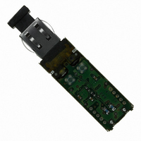
Manufacturer Part Number
HFBR-5912EZ
Description
TXRX OPTICAL 850NM VCSEL MT-RJ
Manufacturer
Avago Technologies US Inc.
Datasheet
1.HFBR-5912EZ.pdf
(13 pages)
Specifications of HFBR-5912EZ
Wavelength
850nm
Voltage - Supply
3.3V
Connector Type
MTRJ
Mounting Type
Through Hole
Function
MMF Transceiver for Gigabit Ethernet, RoHs
Product
Transceiver
Data Rate
1.25 GBd
Maximum Rise Time
0.26 ns/0.4 ns
Maximum Fall Time
0.26 ns/0.4 ns
Pulse Width Distortion
0.227 ns (Max)
Maximum Output Current
30 mA
Operating Supply Voltage
3.14 V to 3.47 V
Maximum Operating Temperature
+ 70 C
Minimum Operating Temperature
0 C
Package / Case
DIP With Connector
Lead Free Status / RoHS Status
Lead free / RoHS Compliant
Applications
-
Lead Free Status / Rohs Status
Lead free / RoHS Compliant
Other names
516-2085
Available stocks
Company
Part Number
Manufacturer
Quantity
Price
Company:

Part Number:
HFBR-5912EZ
Manufacturer:
Avago Technologies US Inc.
Quantity:
135
Company:
Part Number:
HFBR-5912EZ
Manufacturer:
AGILENT
Quantity:
5


Eye Safety Circuit
For an optical transmitter device to be eye-
safe in the event of a single fault failure, the
transmit-ter must either maintain eye-safe
operation or be disabled.
In the HFBR-5912EZ there are three key
elements to the laser driver safety circuitry: a
monitor diode, a window detector circuit, and
direct control of the laser bias. The window
detection circuit monitors the average optical
power using the monitor diode. If a fault
occurs such that the transmitter dc regulation
circuit cannot maintain the preset bias conditions
for the laser emitter within ± 20%, the
transmitter will automatically be disabled. Once
this has occurred, an electrical power reset or
toggling the transmit disable will allow an
attempted turn-on of the transmitter. If fault
remains the transmitter will stay disabled.
Signal Detect
The Signal Detect circuit provides a TTL low
output signal when the optical link is broken
or when the transmitter is OFF as defined by
the Gigabit Ethernet specification IEEE 802.3z,
Table 38.1. The Signal Detect threshold is set
to transition from a high to low state between
the minimum receiver input optional power
and -30 dBm avg. input optical power indicating
a definite optical fault (e.g. unplugged connector
for the receiver or transmitter, broken fiber, or
failed far-end transmitter or data source). A
Signal Detect indicating a working link is
functional when receiving encoded 8B/10B
characters. The Signal Detect does not detect
receiver data error or error-rate. Data errors
can be determined by signal processing offered
by upstream PHY ICs.
Electromagnetic Interference (EMI)
One of a circuit board designer’s foremost
concerns is the control of electromagnetic
emissions from electronic equipment. Success
in controlling generated Electromagnetic
Interference (EMI) enables the designer to pass
a governmental agency’s EMI regulatory standard
and more importantly, it reduces the possibility
of interference to neighboring equipment. Avago
Technologies has designed the HFBR-5912EZ to
provide excellent EMI performance. The EMI
5
performance of a chassis is dependent on
physical design and features which help improve
EMI suppression. Avago Technologies encourages
using standard RF suppression practices and
avoiding poorly EMI-sealed enclosures.
Radiated Emissions for the HFBR-5912EZ have
been tested successfully in several environments.
While this number is important for system
designers in terms of emissions levels inside a
system, Avago Technologies recognizes that the
performance of most interest to our customers
is the emissions levels, which could be expected
to radiate to the outside world from inside a
typical system.
transceivers are intended for use inside an
enclosed system, protruding through the specified
panel opening at the specified protrusion depth.
Along with the system advantage of high port
density comes the increase in the number of
apertures.
the locations of high-speed clocks or gigabit
circuitry with respect to these apertures. While
experimental measurements and experiences do
not indicate any specific transceiver emissions
issues, Avago Technologies recognizes that the
transceiver aperture is often a weak link in
system enclosure integrity and has designed
the modules to minimize emissions and if
necessary, contain the internal system emissions
by shielding the aperture.
To that end, Avago Technologies’ gigabit MT-RJ
transceivers HFBR-5912EZ has a nose shield
which provide a convenient chassis connection
to the nose of the transceiver.
shield improves system EMI performance by
closing off the MT-RJ aperture.
shielding is also improved by tying the four
metal housing package grounding tabs to signal
ground on the PCB.
inspection, the nose shield and metal housing
are electrically separated for customers who do
not wish to directly tie chassis and signal
grounds together.
Figure 6 shows the recommended positioning
of the transceivers with respect to the PCB
and faceplate.
Careful attention must be paid to
In their application, SFF
Though not obvious by
This nose
Localized
Related parts for HFBR-5912EZ
Image
Part Number
Description
Manufacturer
Datasheet
Request
R

Part Number:
Description:
RECEIVER FIBER OPTIC 600NM 40KBD
Manufacturer:
Avago Technologies US Inc.
Datasheet:

Part Number:
Description:
XMITTER FIBER OPTIC 600NM 5MBD
Manufacturer:
Avago Technologies US Inc.
Datasheet:

Part Number:
Description:
XMITTER FIBER OPTIC 600NM 40KBD
Manufacturer:
Avago Technologies US Inc.
Datasheet:

Part Number:
Description:
XMITTER VERSATILE LINK HORZ
Manufacturer:
Avago Technologies US Inc.
Datasheet:

Part Number:
Description:
XMITTER OPT HI PERFORMANCE VERT
Manufacturer:
Avago Technologies US Inc.
Datasheet:

Part Number:
Description:
TXRX FIBER OPTIC 650NM 10MBAUD
Manufacturer:
Avago Technologies US Inc.
Datasheet:
Part Number:
Description:
TXRX FIBER OPTIC 650NM 10MBAUD
Manufacturer:
Avago Technologies US Inc.
Datasheet:

Part Number:
Description:
FIBER OPTIC TRANSMITTER 660NM
Manufacturer:
Avago Technologies US Inc.
Datasheet:

Part Number:
Description:
KIT EVAL FIBER OPTIC 5MBD
Manufacturer:
Avago Technologies US Inc.
Datasheet:
Part Number:
Description:
KIT EVAL FIBER OPTICS 32MBD
Manufacturer:
Avago Technologies US Inc.
Datasheet:

Part Number:
Description:
KIT EVAL FIBER OPTIC 5MBD
Manufacturer:
Avago Technologies US Inc.
Datasheet:

Part Number:
Description:
125MBd 1300nm FiberOptic Eval Kit
Manufacturer:
Avago Technologies US Inc.
Datasheet:

Part Number:
Description:
DC-5MBd 820nm FiberOptic EvalKit
Manufacturer:
Avago Technologies US Inc.
Datasheet:
Part Number:
Description:
125MBd 820nm FiberOptic Eval Kit
Manufacturer:
Avago Technologies US Inc.
Datasheet:
Part Number:
Description:
DC-5MBd 650nm POF Eval Kit
Manufacturer:
Avago Technologies US Inc.
Datasheet: