HFBR-5963LZ Avago Technologies US Inc., HFBR-5963LZ Datasheet - Page 11
HFBR-5963LZ
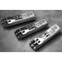
Manufacturer Part Number
HFBR-5963LZ
Description
TXRX MMF FE ATM SONET OC-3 2X5
Manufacturer
Avago Technologies US Inc.
Datasheet
1.HFBR-5963LZ.pdf
(13 pages)
Specifications of HFBR-5963LZ
Applications
Ethernet
Data Rate
155MBd
Wavelength
1300nm
Voltage - Supply
2.97 V ~ 3.63 V
Connector Type
LC Duplex
Mounting Type
Through Hole
Supply Voltage
3.3V
Wavelength Typ
1300nm
Leaded Process Compatible
Yes
Optical Fiber Type
TX/RX
Optical Rise Time
3/2.2ns
Optical Fall Time
3/2.2ns
Jitter
0.4/0.3ns
Operating Temperature Classification
Commercial
Peak Wavelength
1308/1380nm
Package Type
DIP With Connector
Operating Supply Voltage (min)
2.97V
Operating Supply Voltage (typ)
3.3V
Operating Supply Voltage (max)
3.63V
Output Current
50mA
Operating Temp Range
0C to 70C
Mounting
Snap Fit To Panel
Pin Count
10
Lead Free Status / RoHS Status
Lead free / RoHS Compliant
Lead Free Status / RoHS Status
Lead free / RoHS Compliant, Lead free / RoHS Compliant
Available stocks
Company
Part Number
Manufacturer
Quantity
Price

Part Number:
HFBR-5963LZ
Manufacturer:
AVAGO/安华高
Quantity:
20 000


Receiver Optical and Electrical Characteristics
HFBR-5963LZ (T
HFBR-5963ALZ (T
Notes:
1.
2.
3.
4.
5a. The power dissipation of the transmitter is calculated as the sum of
5b. The power dissipation of the receiver is calculated as the sum of
6.
7.
8.
11
Parameter
Input Optical Power at minimum at Window
Edge
Input Optical Power at Eye Center
Input Optical Power Maximum
Operating Wavelength
Systematic Jitter Contributed by the Receiver
OC-3
Duty Cycle Distortion Contributed by the
Receiver FE
Data Dependent Jitter Contributed by the
Receiver FE
Random Jitter Contributed by the Receiver
Signal Detect - Asserted OC-3 FE
Signal Detect - Deasserted
Signal Detect - Hysteresis
Signal Detect Assert Time (off to on)
Signal Detect Deassert Time (on to off )
OC-3
FE
OC-3
FE
OC-3
FE
OC-3
FE
This is the maximum voltage that can be applied across the Differ-
ential Transmitter Data Inputs to prevent damage to the input ESD
protection circuit.
The data outputs are terminated with 50 W connected to V
V. The signal detect output is terminated with 50 W connected to a
pull-up resistor of 4.7 KW tied to V
The power supply current needed to operate the transmitter is
provided to differential ECL circuitry. This circuitry maintains a nearly
constant current flow from the power supply. Constant current
operation helps to prevent unwanted electrical noise from being
generated and conducted or emitted to neighboring circuitry.
This value is measured with the outputs terminated into 50 W
connected to V
average.
the products of supply voltage and current.
the products of supply voltage and currents, minus the sum of the
products of the output voltages and currents.
The data output low and high voltages are measured with respect
to V
The signal detect output low and high voltages are measured with
load condition as mentioned in note 2.
The data output rise and fall times are measured between 20% and
80% levels with the output connected to V
These optical power values are measured with the following con-
ditions: The Beginning of life (BOL) to the End of Life (EOL) optical
power degradation is typically 1.5 dB per the industry convention for
CC
with the output terminated into 50 W connected to V
C
CC
C
= 0 ºC to +70 ºC, V
– 2V and an Input Optical Power level of –14 dBm
= -40 ºC to +85 ºC, V
CC
.
CC
CC
= 2.97 V to 3.63 V)
– 2V through 50W.
CC
= 2.97 V to 3.63 V)
Symbol
P
P
P
l
SJ
DCD
DDJ
RJ
P
P
P
A
A
IN MIN
IN MIN
IN MAX
D
- P
D
(W)
(C)
CC
CC
– 2 V.
– 2
Minimum
-14
-14
1270
P
-45
1.5
0
0
D
+ 1.5 dB
9.
10. The transmitter will provide this low level of Output Optical Power
11. The relationship between Full Width Half Maximum and RMS values
long wavelength LEDs. The actual degradation observed in Avago’s
1300 nm LED products is < 1dB, as specified in this data sheet. Over
the specified operating voltage and temperature ranges. With 25
MBd (12.5 MHz square-wave), input signal. At the end of one meter
of noted optical fiber with cladding modes removed. The average
power value can be converted to a peak power value by adding 3 dB.
Higher output optical power transmitters are available on special
request. Please consult with your local Avago sales representative
for further details.
The Extinction Ratio is a measure of themodulation depth of the
optical signaL. The data “0” output optical power is compared to
the data “1” peak output optical power and expressed as a percent-
age. With the transmitter driven by a 25 MBd (12.5 MHz square-
wave) input signal, the average optical power is measured. The data
“1” peak power is then calculated by adding 3 dB to the measured
average optical power. The data “0” output optical power is found
by measuring the optical power when the transmitter is driven
by a logic “0” input. The extinction ratio is the ratio of the optical
power at the “0” level compared to the optical power at the “1” level
expressed as a percentage or in decibels.
when driven by a Logic “0” input. This can be useful in link trouble-
shooting.
for Spectral Width is derived from the assumption of a Gaussian
shaped spectrum which results in a 2.35 X RMS = FWHM relation-
ship.
Typical
0.2
0.08
0.07
0.3
0.3
2
5
Maximum
-30
-31
-31
-31.8
1380
1.2
0.4
1.0
1.91
2.14
-31-33
100
100
Units
dBm avg
dBm avg
dBm avg
nm
ns p-p
ns p-p
ns p-p
ns p-p
dBm avg
dBm avg
dB
µs
µs
Notes
15a, Figure 8
15b
16a, Figure 8
16b
15a
15b
17a
17b
17c
18a
18b
19
20
21
22
Related parts for HFBR-5963LZ
Image
Part Number
Description
Manufacturer
Datasheet
Request
R

Part Number:
Description:
RECEIVER FIBER OPTIC 600NM 40KBD
Manufacturer:
Avago Technologies US Inc.
Datasheet:

Part Number:
Description:
XMITTER FIBER OPTIC 600NM 5MBD
Manufacturer:
Avago Technologies US Inc.
Datasheet:

Part Number:
Description:
XMITTER FIBER OPTIC 600NM 40KBD
Manufacturer:
Avago Technologies US Inc.
Datasheet:

Part Number:
Description:
XMITTER VERSATILE LINK HORZ
Manufacturer:
Avago Technologies US Inc.
Datasheet:

Part Number:
Description:
XMITTER OPT HI PERFORMANCE VERT
Manufacturer:
Avago Technologies US Inc.
Datasheet:

Part Number:
Description:
TXRX FIBER OPTIC 650NM 10MBAUD
Manufacturer:
Avago Technologies US Inc.
Datasheet:
Part Number:
Description:
TXRX FIBER OPTIC 650NM 10MBAUD
Manufacturer:
Avago Technologies US Inc.
Datasheet:

Part Number:
Description:
FIBER OPTIC TRANSMITTER 660NM
Manufacturer:
Avago Technologies US Inc.
Datasheet:

Part Number:
Description:
KIT EVAL FIBER OPTIC 5MBD
Manufacturer:
Avago Technologies US Inc.
Datasheet:
Part Number:
Description:
KIT EVAL FIBER OPTICS 32MBD
Manufacturer:
Avago Technologies US Inc.
Datasheet:

Part Number:
Description:
KIT EVAL FIBER OPTIC 5MBD
Manufacturer:
Avago Technologies US Inc.
Datasheet:

Part Number:
Description:
125MBd 1300nm FiberOptic Eval Kit
Manufacturer:
Avago Technologies US Inc.
Datasheet:

Part Number:
Description:
DC-5MBd 820nm FiberOptic EvalKit
Manufacturer:
Avago Technologies US Inc.
Datasheet:
Part Number:
Description:
125MBd 820nm FiberOptic Eval Kit
Manufacturer:
Avago Technologies US Inc.
Datasheet:
Part Number:
Description:
DC-5MBd 650nm POF Eval Kit
Manufacturer:
Avago Technologies US Inc.
Datasheet: