TLWY7900 Vishay, TLWY7900 Datasheet
TLWY7900
Specifications of TLWY7900


Related parts for TLWY7900

TLWY7900 Summary of contents
Page 1
... AlInGaP, > for InGaN Parts Table Part Color, Luminous Intensity Red, φ TLWR7900 TLWO7900 Softorange, φ = 2100 mlm (typ.) V Yellow, φ TLWY7900 True green, φ TLWTG7900 Blue green, φ TLWBG7900 Blue, φ TLWB7900 White, φ TLWW7900 Document Number 83144 Rev. 1.7, 24-Jun-04 TLWB / Y7900 ...
Page 2
... TLWB / Y7900 Vishay Semiconductors Absolute Maximum Ratings °C, unless otherwise specified amb TLWR7900 , TLWO7900 , TLWY7900 Parameter = 10 µA Reverse voltage I R ≤ 85 °C DC Forward current T amb ≤ 10 µs Surge forward current t p ≤ 85 °C Power dissipation T amb Junction temperature Operating temperature range Storage temperature range t ≤ ...
Page 3
... Angle of half intensity mA Total included angle Total Flux Captured Forward voltage mA µA Reverse voltage I R Junction capacitance MHz R Temperature coefficient of λ dom F Yellow TLWY7900 Parameter Total flux mA Luminous intensity/Total flux mA Dominant wavelength mA Peak wavelength mA Angle of half intensity mA Total included angle Total Flux Captured ...
Page 4
... TLWB / Y7900 Vishay Semiconductors Blue green TLWBG7900 Parameter Total flux mA Luminous intensity/Total flux mA Dominant wavelength mA Peak wavelength mA Angle of half intensity mA Total included angle Total Flux Captured Forward voltage mA µA Reverse voltage I R Junction capacitance MHz R Temperature coefficient of λ dom F Blue TLWB7900 ...
Page 5
... Figure 5. Forward Current vs. Pulse Length 1.0 0.9 0.8 0.7 120 0.6 16200 Figure 6. Rel. Luminous Intensity vs. Angular Displacement Vishay Semiconductors R = 200 K/W thJA 100 120 T amb - Ambient Temperature ( ° Red, Softorange, ı 85°C T Yellow amb t /T=0 ...
Page 6
... TLWB / Y7900 Vishay Semiconductors 100 100 Total Included Angle (Degrees) 16201 Figure 7. Percentage Total Luminous Flux vs. Total Included Angle for 90 ° emission angle 230 Padsize 8 mm 220 per Anode Pin 210 200 190 180 170 160 0 50 100 150 200 250 ...
Page 7
... Figure 17. Forward Current vs. Forward Voltage 2.0 1.8 1.6 1.4 1.2 1.0 0.8 0.6 0.4 0 0.0 -40 15977 Figure 18. Rel. Luminous Flux vs. Ambient Temperature Vishay Semiconductors Softorange Forward Current ( Yellow – Forward Voltage ( Yellow ...
Page 8
... TLWB / Y7900 Vishay Semiconductors Yellow 1.0 0 Forward Current ( mA ) 15981 F Figure 19. Specific Luminous Flux vs. Forward Current 10 Yellow 1 0.1 0. Forward Current ( mA ) 15979 F Figure 20. Relative Luminous Flux vs. Forward Current 1.2 Yellow 1.1 1.0 0.9 0.8 0.7 0.6 0.5 0.4 0.3 0.2 0.1 0.0 540 550 560 570 580 590 600 610 620 630 640 λ ...
Page 9
... Figure 29. Forward Current vs. Forward Voltage 1.8 1.6 1.4 1.2 1.0 0.8 0.6 0.4 0.2 0.0 -40 -20 T 16061 Figure 30. Rel. Luminous Flux vs. Ambient Temperature Vishay Semiconductors True Green Forward Current ( 3.0 3.5 4.0 4.5 5.0 5 Forward Voltage ( Blue Green ...
Page 10
... TLWB / Y7900 Vishay Semiconductors Blue Green 1.0 0 Forward Current ( mA ) 16059 F Figure 31. Specific Luminous Flux vs. Forward Current 10.00 Blue Green 1.00 0.10 0. Forward Current ( mA ) 16060 F Figure 32. Relative Luminous Flux vs. Forward Current 1.2 Blue Green 1.1 F 1.0 0.9 0.8 0.7 0.6 0.5 0.4 ...
Page 11
... Figure 41. Forward Current vs. Forward Voltage 1.8 1.6 1.4 1.2 1.0 0.8 0.6 0.4 0.2 0.0 -40 -20 T amb - Ambient Temperature ( ° 16065 Figure 42. Rel. Luminous Flux vs. Ambient Temperature Vishay Semiconductors Blue Forward Current ( 3.5 4.0 4.5 5.0 5 Forward Voltage ( White ...
Page 12
... TLWB / Y7900 Vishay Semiconductors White 1.0 0 Forward Current ( mA ) 16063 F Figure 43. Specific Luminous Flux vs. Forward Current 10.00 White 1.00 0.10 0. Forward Current ( mA ) 16064 F Figure 44. Relative Luminous Flux vs. Forward Current 1.2 White 1.1 F 1.0 0.9 0.8 0.7 0.6 0.5 0.4 0.3 0.2 0.1 ...
Page 13
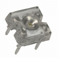
... VISHAY Package Dimensions in mm Document Number 83144 Rev. 1.7, 24-Jun-04 TLWB / Y7900 Vishay Semiconductors 15984 www.vishay.com 13 ...
Page 14
... Various national and international initiatives are pressing for an earlier ban on these substances. Vishay Semiconductor GmbH has been able to use its policy of continuous improvements to eliminate the use of ODSs listed in the following documents. 1. Annex A, B and list of transitional substances of the Montreal Protocol and the London Amendments respectively 2 ...