HSMG-C150 Avago Technologies US Inc., HSMG-C150 Datasheet
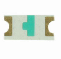
LED 570NM GREEN DIFF 1206 SMD

HSMG-C150

Manufacturer Part Number
HSMG-C150
Description
LED 570NM GREEN DIFF 1206 SMD
Manufacturer
Avago Technologies US Inc.
Type
Uni-Colorr
Datasheets

Specifications of HSMG-C150

Package / Case
1206 (3216 Metric)
Viewing Angle
170°
Color
Green
Millicandela Rating
15mcd
Current - Test
20mA
Wavelength - Dominant
572nm
Wavelength - Peak
570nm
Voltage - Forward (vf) Typ
2.2V
Lens Type
Diffused
Lens Style/size
Rectangle, 2mm x 1.6mm
Size / Dimension
3.20mm L x 1.60mm W
Height
1.10mm
Mounting Type
Surface Mount
Resistance Tolerance
572nm
Led Size
1206
Illumination Color
Green
Lens Color/style
Diffused
Operating Voltage
2.2 V
Wavelength
572 nm
Luminous Intensity
8 mcd
Mounting Style
SMD/SMT
Package Type
Chip Led
Emitting Color
Yellow Green
Test Current (it)
20mA
Forward Current
30mA
Dominant Wave Length
572nm
Forward Voltage
2.6V
Product Length (mm)
3.2mm
Product Height (mm)
1.1mm
Product Depth (mm)
1.6mm
Mounting
Surface Mount
Peak Wavelength
570nm
Shape Type
Rectangular
Chip Material
GaP
Main Category
Chip LED
Number Of Elements
1
Pin Count
2
Operating Temperature Classification
Industrial
Operating Temp Range
-40C to 85C
Reverse Voltage
5V
Power Dissipation
65mW
Lens Dimensions
2x1.6x0.6mm
Lead Free Status / RoHS Status
Lead free / RoHS Compliant
Luminous Flux @ Current - Test
-
Lead Free Status / Rohs Status
Lead free / RoHS Compliant
Other names
516-1443-2

Available stocks

Company
Part Number
Manufacturer
Quantity
Price
Part Number:
HSMG-C150
Manufacturer:
AVAGO
Quantity:
3 031
Part Number:
HSMG-C150
Manufacturer:
Avago Technologies
Quantity:
118 676
Part Number:
HSMG-C150
Manufacturer:
AVAGO/安华高
Quantity:
20 000
Surface Mount Chip LEDs
Technical Data
Features
• Small Size
• Industry Standard Footprint
• Compatible with IR Solder
• Diffused Optics
• Operating Temperature
• Right Angle & Reverse
• Various Colors Available
• Available in 8 mm Tape on
Applications
• Keypad Backlighting
• Push-Button Backlighting
• LCD Backlighting
• Symbol Backlighting
• Front Panel Indicator
Range of -30 C to +85 C
Mount Package Available
7 in. (178 mm) Diameter
Reels
Description
These chip LEDs are designed
in an industry standard package
for ease of handling and use.
Various different LED colors are
available in nine compact, single
color packages.
The HSMx-C150 has the industry
standard 3.2 x 1.6 mm footprint
that is excellent for all around use.
The HSMx-C170 has the widely
used 2.0 x 1.25 mm footprint with
0.8 mm profile. The HSMx-C177
has the widely used 2.0 x 1.25 mm
footprint with 0.4 mm profile. The
HSMx-C19x series has the industry
standard 1.6 x 0.8 mm footprint
with varying profile to suit
designers needs, the HSMx-C190
has 0.8 mm profile, the HSMx-
C191 has a low profile of 0.6 mm,
and the HSMx-C197 has the ultra
low profile of 0.4 mm. This family
with its thin profile and wide
viewing angle makes this LED
exceptional for backlighting
applications.
The HSMx-C110 is a right angle
package with the universally
accepted dimensions of 3.2 x 1.0
x 1.5 mm. The HSMx-C120 is a
smaller right angle package with
industry standard 1.6 x 0.6 x 1.0
mm. HSMx-C265 is a reverse
HSMx-C110/C120/C150/
C170/C177/C190/C191/
C197/C265
mount package with dimensions
of 3.4 x 1.25 x 1.1 mm. These
devices are ideal for LCD
backlighting and sidelighting
applications.
In order to facilitate pick and
place operation, these chip LEDs
are shipped in tape and reel with
4000 units per reel for HSMx-
C120, C170, C177, C190, C191,
C197 packages, and 3000 units
per reel for HSMx-C110, C150,
C265 packages.
All packages are compatible with
IR reflow solder processes. The
small size and wide viewing angle
make these LEDs prime choices
for backlighting applications and
front panel illumination especially
where space is a premium.

Related parts for HSMG-C150

HSMG-C150 Summary of contents

Page 1

Surface Mount Chip LEDs Technical Data Features • Small Size • Industry Standard Footprint • Compatible with IR Solder • Diffused Optics • Operating Temperature Range of - +85 C • Right Angle & Reverse Mount Package Available ...

Page 2

... Device Selectiion Guide GaP Green HER HSMG-C110 HSMS-C110 HSMG-C120 HSMS-C120 HSMG-C150 HSMS-C150 HSMG-C170 HSMS-C170 HSMG-C177 HSMS-C177 HSMG-C190 HSMS-C190 HSMG-C191 HSMS-C191 HSMG-C197 HSMS-C197 HSMG-C265 – As AlGaAs Red HSMH-C110 Untinted, Non-Diffused HSMH-C120 Untinted, Non-Diffused HSMH-C150 Untinted, Diffused HSMH-C170 Untinted, Diffused HSMH-C190 Untinted, Diffused ...

Page 3

Package Dimensions LED DIE 0.8 (0.031) 3.2 (0.126 ) DIFFUSED 2.0 (0.079) EPOXY 0.6 (0.024) PC BOARD CATHODE LINE 0.5 (0.020) 0.50 ± 0.2 (0.020 ± 0.008) SOLDERING TERMINAL HSMx-C150 CATHODE MARK LED DIE 0.4 (0.016) 1.6 (0.063 ) 1.0 ...

Page 4

CATHODE LED DIE MARK 0.4 (0.016) 1.6 (0.063 ) 1.0 (0.039) 0.3 (0.012) DIFFUSED EPOXY PC BOARD 0.8 (0.031) 0.26 (0.010) CATHODE LINE 0.3 ± 0.15 0.3 ± 0.15 (0.012 ± 0.006) (0.012 ± 0.006) 0.7 (0.028) MIN. SOLDERING TERMINAL ...

Page 5

CATHODE MARK (ANODE MARK FOR HSMH-C120) LED DIE 0.3 (0.012) 0.6 (0.024) 1.6 (0.063) 1.2 (0.047) CLEAR EPOXY 1.0 (0.039) PC BOARD 0.4 (0.016) 3 – 0.3 (0.012) CATHODE LINE SOLDERING TERMINAL HSMx-C120 Notes: 1. All dimensions in millimeters (inches). ...

Page 6

... Notes: 1. Derate linearly as shown in Figure 4 for temperature above Pulse condition of 1/10 duty and 0.1 msec. width. Electrical Characteristics at T Part Number HSMS-C110/150 HSMS-C120 HSMS-C170/177/190/191/197 HSMD-C110/150 HSMD-C120 HSMD-C170/177/190/191/197 HSMY-C110/150 HSMY-C170/190/191/197 HSMG-C110/150 HSMG-C120 HSMG-C170/177/190191/197/265 HSMH-C110/150 HSMH-C120 HSMH-C170/190/191/265 = C110/150/265 C120/170/177/190/191/197 25 100 -30 to +85 -40 to +85 See reflow soldering profile (Figure 9 & ...

Page 7

... Optical Characteristics at T Part Number HSMG-C110/177/197 HSMG-C120 HSMG-C150/170/190/191/265 HSMS-C110/177/197 HSMS-C120 HSMS-C150/170/190/191 HSMD-C110/177/197 HSMD-C120 HSMD-C150/170/190/191 HSMY-C110/197 HSMY-C150/170/190/191 HSMH-C110 HSMH-C120 HSMH-C150/170/190/191/265 Notes: 1. The luminous intensity, Iv, is measured at the peak of the spatial radiation pattern, which may not be aligned with the mechanical axis of the lamp package. ...

Page 8

Light Intensity (Iv) Bin Limits Intensity (mcd) Bin ID Min. Max. A 0.11 0.18 B 0.18 0.29 C 0.29 0.45 D 0.45 0.72 E 0.72 1.10 F 1.10 1.80 G 1.80 2.80 H 2.80 4.50 J 4.50 7.20 K 7.20 ...

Page 9

ANGLE 1.00 0.90 0.80 0.70 0.60 0.50 0.40 0.30 0.20 0.10 0 -90 -80 -70 -60 -50 -40 -30 ...

Page 10

ANGLE Figure 7. Relative Intensity vs. Angle for HSMx-C177 and C197. 1.00 0.90 0.80 0.70 0.60 0.50 0.40 0.30 ...

Page 11

Figure 14. Recommended Soldering Pattern for HSMx-C110. 2.2 (0.087) DIA. PCB HOLE 1.4 2.3 1.4 (0.055) (0.091) (0.055) Figure 16. Recommended Soldering Pattern for HSMx-C265. 3.0 ...

Page 12

DIM. A (SEE TABLE 1) DIM. B (SEE TABLE 1) 2.00 ± 0.05 (0.079 ± 0.002) 4.00 (0.157) HSMx-C110/C120 POSITION IN CARRIER TAPE DIM. A (SEE TABLE 1) R 1.0 ± 0.05 DIM. B (0.039 ± 0.002) (SEE ...

Page 13

END THERE SHALL BE A MOUNTED WITH MINIMUM OF 160 mm COMPONENTS (6.3 INCH) OF EMPTY COMPONENT POCKETS SEALED WITH COVER TAPE. Figure 20. Tape Leader and Trailer Dimensions. Notes: 1. All dimensions in millimeters (inches). 2. Tolerance is 0.1 ...

Related keywords