LTL-1CHG Lite-On Electronics, LTL-1CHG Datasheet - Page 5
LTL-1CHG
Manufacturer Part Number
LTL-1CHG
Description
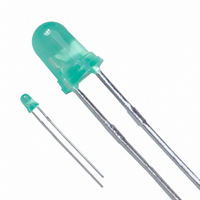
LED 3MM GREEN DIFFUSED
Manufacturer
Lite-On Electronics
Type
Uni-Colorr
Specifications of LTL-1CHG
Led Size
T-1
Illumination Color
Green
Lens Color/style
Diffused
Operating Voltage
2.6 V
Wavelength
565 nm
Luminous Intensity
12.6 mcd
Operating Current
30 mA
Lens Shape
Dome
Mounting Style
Through Hole
Viewing Angle
60°
Package / Case
Radial - 2 Lead
Color
Green
Millicandela Rating
12.6mcd
Current - Test
10mA
Wavelength - Dominant
569nm
Wavelength - Peak
565nm
Voltage - Forward (vf) Typ
2.1V
Lens Type
Diffused, Green Tinted
Lens Style/size
Round, 3.1mm
Height
5.20mm
Mounting Type
Through Hole
Resistance Tolerance
569nm
Emitting Color
Yellow Green
Test Current (it)
100mA
Forward Current
30mA
Dominant Wave Length
569nm
Forward Voltage
2.6V
Product Length (mm)
3.8mm
Product Height (mm)
5.2mm
Product Depth (mm)
3.8mm
Mounting
Through Hole
Peak Wavelength
565nm
Shape Type
Circular
Main Category
Standard LED
Number Of Elements
1
Pin Count
2
Operating Temperature Classification
Industrial
Operating Temp Range
-55C to 100C
Reverse Voltage
5V
Power Dissipation
100mW
Lens Dimensions
3.1x3.1x4.1mm
Lead Free Status / RoHS Status
Lead free / RoHS Compliant
Luminous Flux @ Current - Test
-
Lead Free Status / Rohs Status
Lead free / RoHS Compliant
Other names
160-1710
Available stocks
Company
Part Number
Manufacturer
Quantity
Price
Company:

Part Number:
LTL-1CHG
Manufacturer:
LITEON
Quantity:
40 000
Company:
Part Number:
LTL-1CHG-001A
Manufacturer:
LITEON
Quantity:
40 000
Company:
Part Number:
LTL-1CHG-002
Manufacturer:
LITEON
Quantity:
40 000
Company:
Part Number:
LTL-1CHG-002A
Manufacturer:
LITEON
Quantity:
40 000
Company:
Part Number:
LTL-1CHG-011
Manufacturer:
LITEON
Quantity:
40 000


6. Drive Method
2. Storage
3. Cleaning
4. Lead Forming & Assembly
1. Application
5. Soldering
BNS-OD-C131/A4
Part No. : LTL-1CHGH132
parallel in an application; it is recommended that a current limiting resistor be incorporated in the drive circuit. In
series with each LED as shown in Circuit A below.
applications in which exceptional reliability is required, particularly when the failure or malfunction of the
LEDs may directly jeopardize life or health (such as in aviation, transportation, traffic control equipment,
medical and life support systems and safety devices).
The storage ambient for the LEDs should not exceed 30°C temperature or 70% relative humidity. It is
recommended that LEDs out of their original packaging are used within three months.
For extended storage out of their original packaging, it is recommended that the LEDs be stored in a sealed
container with appropriate desiccant or in a dessicator with nitrogen ambient.
Use alcohol-based cleaning solvents such as isopropyl alcohol to clean the LEDs if necessary.
During lead forming, the leads should be bent at a point at least 3mm from the base of LED lens. Do not use
the base of the leadframe as a fulcrum during forming. Lead forming must be done before soldering at normal
When soldering, leave a minimum of 2mm clearance from the base of the lens to the soldering point.
Dipping the lens into the solder must be avoided.
Do not apply any external stress to the lead frame during soldering while the LED is at high temperature.
Recommended soldering condition (for Lamp):
An LED is a current operated device, In order to ensure intensity uniformity on multiple LEDs connected in
The LEDs described here are intended to be used for ordinary electronic equipment (such as office equipment,
communication equipment and household applications). Consult Liteon’s Sales in advance for information on
temperature. During assembly on PCB, use minimum clinch force possible to avoid excessive mechanical stress
Note: Excessive soldering temperature and/or time might result in deformation of the LED lens or catastrophic
failure of the LED. IR re-flow is not suitable process for through hole type LED lamp production.
Temperature
Soldering time
Circuit model A
Soldering iron
LED
300°C Max.
3 sec. Max.
(one time only)
LITE-ON TECHNOLOGY CORPORATION
Circuit model B
P r o p e r t y o f L i t e - O n O n l y
Pre-heat
Pre-heat time
Solder wave
Soldering time
LED
CAUTIONS
Wave soldering
100°C Max.
60 sec. Max.
260°C Max.
10 sec. Max.
(A) Recommended circuit.
(B) The brightness of each LED might
appear different due to the differences
in the I-V characteristics of those
LEDs
Page :
5
of
6
Related parts for LTL-1CHG
Image
Part Number
Description
Manufacturer
Datasheet
Request
R

Part Number:
Description:
LED 3MM HI-EFF RED DIFFUSED
Manufacturer:
Lite-On Electronics
Datasheet:

Part Number:
Description:
Standard LED - Through Hole Red Diffused
Manufacturer:
Lite-On Electronics
Datasheet:
Part Number:
Description:
LED T-1 5V ORG DIFF W/INT RES
Manufacturer:
Lite-On Electronics
Datasheet:

Part Number:
Description:
LED 5MM HI-EFF RED TRANS
Manufacturer:
Lite-On Electronics
Datasheet:

Part Number:
Description:
LED 5MM YELLOW DIFFUSED
Manufacturer:
Lite-On Electronics
Datasheet:

Part Number:
Description:
LED 3MM HI-EFF RED TRANSPARENT
Manufacturer:
Lite-On Electronics
Datasheet:

Part Number:
Description:
LED RED 5MM ALINGAP 632NM
Manufacturer:
Lite-On Electronics
Datasheet:
Part Number:
Description:
LED YELL-ORANG 5MM ALINGAP 611NM
Manufacturer:
Lite-On Electronics
Datasheet:
Part Number:
Description:
LED AMBER YELL 5MM ALINGAP 595NM
Manufacturer:
Lite-On Electronics
Datasheet:
Part Number:
Description:
T1-3/4 YELLOW DIFF NO FLANGE
Manufacturer:
Lite-On Electronics
Part Number:
Description:
LED SUPER RED 5MM ALINGAP 639NM
Manufacturer:
Lite-On Electronics
Datasheet:
Part Number:
Description:
LED YELLOW 5MM ALINGAP 588NM
Manufacturer:
Lite-On Electronics
Datasheet:
Part Number:
Description:
LED RES LAMP 3MM 5V RED DIFFUSED
Manufacturer:
Lite-On Electronics
Datasheet:
Part Number:
Description:
LED RES LAMP 3MM 12V RED DIFF
Manufacturer:
Lite-On Electronics
Datasheet:
Part Number:
Description:
LED W/INT RES 3MM 5V GREEN DIFF
Manufacturer:
Lite-On Electronics
Datasheet: