HLMP-1521 Avago Technologies US Inc., HLMP-1521 Datasheet - Page 3
HLMP-1521
Manufacturer Part Number
HLMP-1521
Description
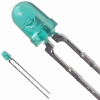
LED 3MM 569NM GREEN TINT
Manufacturer
Avago Technologies US Inc.
Type
Uni-Colorr
Specifications of HLMP-1521
Viewing Angle
45°
Package / Case
Radial - 2 Lead
Color
Green
Millicandela Rating
22mcd
Current - Test
10mA
Wavelength - Dominant
569nm
Wavelength - Peak
565nm
Voltage - Forward (vf) Typ
2.1V
Lens Type
Clear, Green Tinted
Lens Style/size
Round, 3mm, T-1
Height
4.70mm
Mounting Type
Through Hole
Resistance Tolerance
569nm
Led Size
T-1
Illumination Color
Green
Lens Color/style
Tinted Non-Diffused
Operating Voltage
2.1 V
Wavelength
569 nm
Luminous Intensity
22 mcd
Operating Current
10 mA
Lens Dimensions
3 mm
Lens Shape
Dome
Maximum Operating Temperature
+ 100 C
Minimum Operating Temperature
- 20 C
Mounting Style
Through Hole
Color, Emitted
Green
Finish, Lens
Diffused
Package Type
3 mm (T-1)
Emitting Color
Yellow Green
Test Current (it)
10mA
Forward Current
30mA
Dominant Wave Length
569nm
Forward Voltage
2.7V
Product Length (mm)
3.43mm
Product Height (mm)
4.7mm
Product Depth (mm)
3.43mm
Mounting
Through Hole
Peak Wavelength
565nm
Shape Type
Circular
Chip Material
GaP
Main Category
Standard LED
Number Of Elements
1
Pin Count
2
Operating Temperature Classification
Commercial
Operating Temp Range
-20C to 100C
Reverse Voltage
5V
Power Dissipation
135mW
Lead Free Status / RoHS Status
Lead free / RoHS Compliant
Luminous Flux @ Current - Test
-
Lead Free Status / Rohs Status
Lead free / RoHS Compliant
Other names
516-1298
Available stocks
Company
Part Number
Manufacturer
Quantity
Price
Company:

Part Number:
HLMP-1521
Manufacturer:
AVAGO
Quantity:
50 000
Company:
Part Number:
HLMP-1521-E0002
Manufacturer:
AVAGO
Quantity:
40 000
Company:
Part Number:
HLMP-1521-E0002
Manufacturer:
AVAGO
Quantity:
50 000
Company:
Part Number:
HLMP-1521-E00A2
Manufacturer:
AVAGO
Quantity:
40 000
Company:
Part Number:
HLMP-1521-E00A2
Manufacturer:
AVAGO
Quantity:
50 000


Electrical Characteristics at T
Notes:
1. q
2. The dominant wavelength, l
3. Radiant intensity, I
3
Symbol
I
2q
l
Dl
l
t
C
Rq
V
V
h
V
s
PEAK
d
F
R
V
the device.
luminous efficacy in lumens/watt.
1
J-PIN
1/2
1
/
/
2
2
is the off-axis angle at which the luminous intensity is half the axial luminous intensity.
Description
Luminous Intensity
Including Angle Between
Half Luminous Intensity
Points
Peak Wavelength
Spectral Line Halfwidth
Dominant Wavelength
Speed of Response
Capacitance
Thermal Resistance
Forward Voltage
Reverse Breakdown Voltage
Luminous Efficacy
e
, in watts/steradian, may be found from the equation I
A
d
, is derived from the CIE chromaticity diagram and represents the single wavelength which defines the color of
= 25°C
1320
1321
1420
1421
1520
1521
All
132x
142X
152X
132x
142X
152X
132x
142X
152X
132x
142X
152X
132x
142X
152X
All
132x
142X
152X
All
132x
142X
152X
Device
HLMP-
8.6
8.6
9.2
9.2
6.7
6.7
5.0
Min.
e
= l
v
/h
30
30
15
15
22
22
45
635
583
565
40
36
28
626
585
569
90
90
500
11
15
18
290
1.9
2.0
2.1
145
500
595
v
Typ.
, where l
v
is the luminous intensity in candelas and h
2.4
2.4
2.7
Max.
mcd
mcd
mcd
Deg.
nm
nm
nm
ns
pF
°C/W
V
V
lumens
watt
Units
Test Conditions
I
(Figure 3)
I
(Figure 8)
I
(Figure 3)
I
See Note 1
(Figures 6, 11, 16, 21)
Measurement
at Peak (Figure 1)
See Note 2 (Figure 1)
V
Junction to
Cathode Lead
I
I
See Note 3
F
F
F
F
F
R
F
= 10 mA
= 10 mA
= 10 mA
= 10 mA
= 10 mA
= 100 µA
= 0; f = 1 MHz
v
is the
Related parts for HLMP-1521
Image
Part Number
Description
Manufacturer
Datasheet
Request
R

Part Number:
Description:
LED 3MM 569NM GREEN DIFF
Manufacturer:
Avago Technologies US Inc.
Datasheet:

Part Number:
Description:
LED 5MM 639NM RED WATER CLEAR
Manufacturer:
Avago Technologies US Inc.
Datasheet:

Part Number:
Description:
LED 5MM 635NM HE RED WATER CLEAR
Manufacturer:
Avago Technologies US Inc.
Datasheet:

Part Number:
Description:
LED Lamp
Manufacturer:
Avago Technologies US Inc.
Datasheet:
Part Number:
Description:
LED, T-1 3/4, RED, 8.6MCD, 626NM
Manufacturer:
Avago Technologies US Inc.
Datasheet:

Part Number:
Description:
LED 5MM FLAT TOP INGAN WHITE
Manufacturer:
Avago Technologies US Inc.
Datasheet:
Part Number:
Description:
LED 5MM FLAT TOP INGAN WHITE
Manufacturer:
Avago Technologies US Inc.
Datasheet:
Part Number:
Description:
LED 5MM FLAT TOP INGAN WHITE
Manufacturer:
Avago Technologies US Inc.
Datasheet:
Part Number:
Description:
LED 5MM FLAT TOP INGAN WHITE
Manufacturer:
Avago Technologies US Inc.
Datasheet:

Part Number:
Description:
GREEN T-1 LED MAX 34MCD
Manufacturer:
Avago Technologies US Inc.
Datasheet:

Part Number:
Description:
LED T 1 3/4 OR 5MM AMBER
Manufacturer:
Avago Technologies US Inc.
Datasheet:
Part Number:
Description:
YELLOW T-1 LED MAX 75MCD
Manufacturer:
Avago Technologies US Inc.
Datasheet:
Part Number:
Description:
LED, T-1 3/4, BLUE, 1500MCD, 470NM
Manufacturer:
Avago Technologies US Inc.
Datasheet:
Part Number:
Description:
LED, T-1 3/4, BLUE, 5500MCD, 470NM
Manufacturer:
Avago Technologies US Inc.
Datasheet:
Part Number:
Description:
LED, T-1 3/4, RED, 2.1MCD, 626NM
Manufacturer:
Avago Technologies US Inc.
Datasheet: