HLMP-S201 Avago Technologies US Inc., HLMP-S201 Datasheet - Page 4
HLMP-S201
Manufacturer Part Number
HLMP-S201
Description
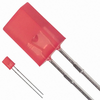
LED 2X5MM 635NM HE RED DIFF
Manufacturer
Avago Technologies US Inc.
Datasheet
1.HLMP-S201.pdf
(8 pages)
Specifications of HLMP-S201
Viewing Angle
110°
Color
Red
Millicandela Rating
3.5mcd
Current - Test
20mA
Wavelength - Dominant
626nm
Wavelength - Peak
635nm
Voltage - Forward (vf) Typ
1.9V
Lens Type
Diffused, Red Tinted
Lens Style/size
Rectangle, 5mm x 2mm
Package / Case
Radial - 2 Lead
Height
8.00mm
Mounting Type
Through Hole
Resistance Tolerance
626nm
Led Size
2 mm x 5 mm
Illumination Color
High Efficiency Red
Lens Color/style
Tinted Diffused
Operating Voltage
1.9 V
Wavelength
626 nm
Operating Current
20 mA
Lens Dimensions
2 mm x 5 mm
Lens Shape
Rectangular
Maximum Operating Temperature
+ 100 C
Minimum Operating Temperature
- 40 C
Mounting Style
Through Hole
Lead Free Status / RoHS Status
Lead free / RoHS Compliant
Luminous Flux @ Current - Test
-
Lead Free Status / Rohs Status
Lead free / RoHS Compliant
Other names
516-1282
Available stocks
Company
Part Number
Manufacturer
Quantity
Price
Company:

Part Number:
HLMP-S201
Manufacturer:
AVAGO
Quantity:
40 000
Company:
Part Number:
HLMP-S201
Manufacturer:
AVAGO
Quantity:
50 000
Company:
Part Number:
HLMP-S201-D0000
Manufacturer:
AVAGO
Quantity:
40 000
Company:
Part Number:
HLMP-S201-D0000
Manufacturer:
AVAGO
Quantity:
50 000
Company:
Part Number:
HLMP-S201-D0002
Manufacturer:
AVAGO
Quantity:
40 000


Absolute Maximum Ratings at T
Parameter
Peak Forward Current
Average Forward Current
DC Current
Transient Forward Current
(10 µsec Pulse)
LED Junction Temperature
Operating Temperature Range
Storage Temperature Range
Notes:
1. See Figure 5 to establish pulsed operating conditions.
2. For AlGaAs Red, Red, Orange, and Green series derate linearly from 50°C at 0.5 mA/°C. For Yellow series derate linearly from 50°C at 0.34 mA/°C.
3. The transient peak current is the maximum non-recurring peak current that can be applied to the device without damaging the LED die and wire
4
Figure 1. Relative intensity vs. wavelength.
bond. It is not recommended that the device be operated at peak currents beyond the peak forward current listed in the Absolute Maximum
Ratings.
1.0
0.5
0
500
HIGH
PERFORMANCE
GREEN
[2]
EMERALD GREEN
YELLOW
550
[1]
[3]
A
= 25°C
AlGaAs Red
300
20
30
500
110
-20 to +100
-40 to +100
600
ORANGE
WAVELENGTH – nm
650
High Efficiency Red/
Orange
90
25
30
500
110
-40 to +100
-40 to +100
AlGaAs RED
HIGH EFFICIENCY RED
700
T
A
Green/
Yellow
60
20
20
500
110
-40 to +100
-40 to +100
= 25 C
750
Emerald Green
90
25
30
500
110
-20 to +100
-40 to +100
Units
mA
mA
mA
mA
°C
°C
°C
Related parts for HLMP-S201
Image
Part Number
Description
Manufacturer
Datasheet
Request
R

Part Number:
Description:
LED 3MM 569NM GREEN DIFF
Manufacturer:
Avago Technologies US Inc.
Datasheet:

Part Number:
Description:
LED 5MM 635NM HE RED WATER CLEAR
Manufacturer:
Avago Technologies US Inc.
Datasheet:

Part Number:
Description:
LED 5MM 639NM RED WATER CLEAR
Manufacturer:
Avago Technologies US Inc.
Datasheet:

Part Number:
Description:
LED LT BAR 8.89X3.81MM SGL GREEN
Manufacturer:
Avago Technologies US Inc.
Datasheet:

Part Number:
Description:
LED LT BAR 19.05X3.81MM SGL YLW
Manufacturer:
Avago Technologies US Inc.
Datasheet:

Part Number:
Description:
LED Lamp
Manufacturer:
Avago Technologies US Inc.
Datasheet:

Part Number:
Description:
LED 5MM FLAT TOP INGAN WHITE
Manufacturer:
Avago Technologies US Inc.
Datasheet:
Part Number:
Description:
LED 5MM FLAT TOP INGAN WHITE
Manufacturer:
Avago Technologies US Inc.
Datasheet:
Part Number:
Description:
LED 5MM FLAT TOP INGAN WHITE
Manufacturer:
Avago Technologies US Inc.
Datasheet:
Part Number:
Description:
LED 5MM FLAT TOP INGAN WHITE
Manufacturer:
Avago Technologies US Inc.
Datasheet:

Part Number:
Description:
LED DOME 5V 635NM HER DFF RA AXL
Manufacturer:
Avago Technologies US Inc.
Datasheet:

Part Number:
Description:
LED DOME 5V 565NM GN DIFF RA AXL
Manufacturer:
Avago Technologies US Inc.
Datasheet:

Part Number:
Description:
LED DOME 583NM YLW DIFF RA AXIAL
Manufacturer:
Avago Technologies US Inc.
Datasheet:

Part Number:
Description:
LED 5MM GAP GRN RA HOUSING TH
Manufacturer:
Avago Technologies US Inc.
Datasheet:

Part Number:
Description:
LED 3MM GAP DIFF RED RA HOUSING
Manufacturer:
Avago Technologies US Inc.
Datasheet: