HLMP-4101 Avago Technologies US Inc., HLMP-4101 Datasheet - Page 3
HLMP-4101
Manufacturer Part Number
HLMP-4101
Description
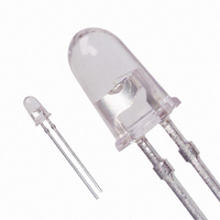
LED 5MM 650NM HE RED WATER CLEAR
Manufacturer
Avago Technologies US Inc.
Specifications of HLMP-4101
Viewing Angle
8°
Package / Case
Radial - 2 Lead
Color
Red
Millicandela Rating
1000mcd
Current - Test
20mA
Wavelength - Dominant
642nm
Wavelength - Peak
650nm
Voltage - Forward (vf) Typ
1.8V
Lens Type
Clear
Lens Style/size
Round, 5mm, T-1 3/4
Height
9.19mm
Mounting Type
Through Hole
Resistance Tolerance
642nm
Led Size
T-1 3/4
Illumination Color
Deep Red
Lens Color/style
Non-Diffused
Operating Voltage
1.8 V
Wavelength
642 nm
Luminous Intensity
1000 mcd
Operating Current
20 mA
Lens Dimensions
5 mm
Lens Shape
Dome
Maximum Operating Temperature
+ 100 C
Minimum Operating Temperature
- 20 C
Mounting Style
Through Hole
Color, Emitted
Red
Finish, Lens
Diffused
Package Type
5 mm (T-13⁄4)
Lead Free Status / RoHS Status
Lead free / RoHS Compliant
Luminous Flux @ Current - Test
-
Lead Free Status / Rohs Status
Lead free / RoHS Compliant
Other names
516-1393
Available stocks
Company
Part Number
Manufacturer
Quantity
Price
Company:

Part Number:
HLMP-4101
Manufacturer:
AVAGO
Quantity:
40 000
Company:
Part Number:
HLMP-4101
Manufacturer:
AVAGO
Quantity:
50 000


Absolute Maximum Ratings at T
Notes:
1. Maximum I
2. Refer to Figure 6 to establish pulsed operating conditions.
3. Derate linerally as shown in Figure 5.
4. The transient peak current is the maximum non-recurring peak current the device can withstand without
Electrical/Optical Characteristics at T
Notes:
1. The dominant wavelength, λ
2. The radiant intensity, I
3. The approximate total luminous flux output within a cone angle of 2θ about the optical axis, φ
3
Parameter
Peak Forward Current
Average Forward Current
DC Current
Power Dissipation
Reverse Voltage (I
Transient Forward Current (10 μs Pulse)
Operating Temperature Range
Storage Temperature Range
Symbol
V
V
λ
λ
Δλ
τ
C
θ
η
s
PEAK
d
Jc
F
R
V
damaging the LED die and wire bonds. It is not recommended that the device be operated at peak currents
beyond the Absolute Maximum Peak Forward Current.
luminous efficacy in lumens/watt.
φ
1/2
v
(2θ) = [φ
[3]
v
PEAK
(θ)/I
Description
Forward Voltage
Reverse Breakdown Voltage
Peak Wavelength
Dominant Wavelength
Spectral Line Halfwidth
Speed of Response
Capacitance
Thermal Resistance
Luminous Efficacy
v
at f = 1 kHz, DF = 6.7%.
(0)]I
R
= 100 μA)
v
; Where: φ
[1, 2]
e
, in watts per steradian, may be found from the equation I
[2]
d
, is derived from the CIE chromaticity diagram and represents the color of the device.
v
(θ)/I
A
= 25°C
v
(0) is obtained from Figure 7.
A
= 25°C
[4]
Maximum Rating
300
20
30
87
5
500
-20 to +100
-40 to +100
Min.
5.0
Typ.
1.8
15.0
650
642
20
30
30
220
80
e
= I
v
/η
Units
mA
mA
mA
mW
V
mA
°C
°C
v
, where Iv is the luminous intensity in candelas and η
v
(2θ), may be obtained from the following formula:
Max.
2.42
Units
V
V
nm
nm
nm
ns
pF
°C/W
l m/W
Test Conditions
20 mA
I
Measurement at
Peak
Note 1
Exponential Time
Constant, e-
V
Junction to
Cathode Lead
Note 2
R
F
= 100 μA
= 0; f = 1 MHz
t/2
v
is
Related parts for HLMP-4101
Image
Part Number
Description
Manufacturer
Datasheet
Request
R

Part Number:
Description:
LED 5MM 635NM HE RED WATER CLEAR
Manufacturer:
Avago Technologies US Inc.
Datasheet:

Part Number:
Description:
LED 5MM 639NM RED WATER CLEAR
Manufacturer:
Avago Technologies US Inc.
Datasheet:

Part Number:
Description:
LED LT BAR 19.05X3.81MM SGL YLW
Manufacturer:
Avago Technologies US Inc.
Datasheet:

Part Number:
Description:
LED Lamp
Manufacturer:
Avago Technologies US Inc.
Datasheet:

Part Number:
Description:
LED T1 3/4 5MM WHT PREC OPT PREF
Manufacturer:
Avago Technologies US Inc.
Datasheet:
Part Number:
Description:
LED, T-1 3/4, RED, 8.6MCD, 626NM
Manufacturer:
Avago Technologies US Inc.
Datasheet:

Part Number:
Description:
LED 5MM FLAT TOP INGAN WHITE
Manufacturer:
Avago Technologies US Inc.
Datasheet:
Part Number:
Description:
LED 5MM FLAT TOP INGAN WHITE
Manufacturer:
Avago Technologies US Inc.
Datasheet:
Part Number:
Description:
LED 5MM FLAT TOP INGAN WHITE
Manufacturer:
Avago Technologies US Inc.
Datasheet:
Part Number:
Description:
LED 5MM FLAT TOP INGAN WHITE
Manufacturer:
Avago Technologies US Inc.
Datasheet:

Part Number:
Description:
LED T 1 3/4 OR 5MM AMBER
Manufacturer:
Avago Technologies US Inc.
Datasheet:

Part Number:
Description:
LED T1-3/4 SUPER BRIGHT GREEN
Manufacturer:
Avago Technologies US Inc.
Part Number:
Description:
LED LIGHT BAR, 4, RED, 23MCD
Manufacturer:
Avago Technologies US Inc.
Datasheet:
Part Number:
Description:
LED LIGHT BAR, 4, GREEN, 25MCD
Manufacturer:
Avago Technologies US Inc.
Datasheet:
Part Number:
Description:
LED, T-1 3/4, BLUE, 1500MCD, 470NM
Manufacturer:
Avago Technologies US Inc.
Datasheet: