HLMP-3601 Avago Technologies US Inc., HLMP-3601 Datasheet - Page 5
HLMP-3601
Manufacturer Part Number
HLMP-3601
Description
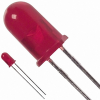
LED 5MM 12V 635NM HE RED DIFF
Manufacturer
Avago Technologies US Inc.
Datasheet
1.HLMP-1640.pdf
(9 pages)
Specifications of HLMP-3601
Viewing Angle
60°
Package / Case
Radial - 2 Lead
Color
Red
Millicandela Rating
2.1mcd
Current - Test
13mA
Wavelength - Dominant
626nm
Wavelength - Peak
635nm
Lens Type
Diffused, Red Tinted
Lens Style/size
Round, 5mm, T-1 3/4
Height
8.81mm
Mounting Type
Through Hole
Resistance Tolerance
626nm
Led Size
T-1 3/4
Illumination Color
High Efficiency Red
Lens Color/style
Tinted Diffused
Operating Voltage
12 V
Wavelength
626 nm
Luminous Intensity
2.1 mcd
Operating Current
13 mA
Lens Dimensions
5 mm
Lens Shape
Dome
Maximum Operating Temperature
+ 85 C
Minimum Operating Temperature
- 40 C
Mounting Style
Through Hole
Bulb Size
T-1 3/4 (5mm)
Led Color
Red
Forward Current If
13mA
Forward Voltage
15V
Led Mounting
Through Hole
Wavelength Typ
626nm
Rohs Compliant
Yes
Lead Free Status / RoHS Status
Lead free / RoHS Compliant
Voltage - Forward (vf) Typ
-
Luminous Flux @ Current - Test
-
Lead Free Status / Rohs Status
Lead free / RoHS Compliant
Other names
516-1340
Available stocks
Company
Part Number
Manufacturer
Quantity
Price
Company:

Part Number:
HLMP-3601
Manufacturer:
AVAGO
Quantity:
40 000
Company:
Part Number:
HLMP-3601
Manufacturer:
AVAGO
Quantity:
50 000


Figure 1. Forward current vs. applied forward voltage. 5 volt devices.
Figure 3. Maximum allowed applied forward voltage vs.
ambient temperature Rq
Figure 5. Relative luminous intensity vs. angular displacement for T-1
package.
5
90°
80°
70°
7.5
24
20
16
12
60°
8
4
0
8
6
4
2
0
0
0
50°
V
CC
T
2
A
40°
– APPLIED FORWARD VOLTAGE – V
– AMBIENT TEMPERATURE – °C
20
4
30°
6
20°
JA
40
7.5
= 175°C/W. 5 volt devices.
8
10°
10
60
0°
12
1.0
0.8
0.6
0.4
0.2
10°
14
20°
80
15
85
30°
16
40°
50°
60°
70°
80°
90°
100°
Figure 2. Forward current vs. applied forward voltage. 12 volt devices.
Figure 4. Maximum allowed applied forward voltage vs.
ambient temperature Rq
Figure 6. Relative luminous intensity vs. angular displacement for T-1
package.
90°
80°
70°
24
20
16
12
16
15
12
60°
8
4
0
8
4
0
0
0
50°
V
CC
T
2
40°
A
– APPLIED FORWARD VOLTAGE – V
– AMBIENT TEMPERATURE – °C
20
4
30°
6
20°
JA
40
7.5
= 175°C/W. 12 volt devices.
8
10°
10
60
0°
0.8
0.6
0.4
0.2
12
1.0
10°
14
20°
80
15
85
30°
16
40°
50°
60°
70°
80° 90°
3
/
4
100°
Related parts for HLMP-3601
Image
Part Number
Description
Manufacturer
Datasheet
Request
R

Part Number:
Description:
LED 5MM 639NM RED WATER CLEAR
Manufacturer:
Avago Technologies US Inc.
Datasheet:

Part Number:
Description:
LED 5MM 635NM HE RED WATER CLEAR
Manufacturer:
Avago Technologies US Inc.
Datasheet:

Part Number:
Description:
LED 3MM 569NM GREEN DIFF
Manufacturer:
Avago Technologies US Inc.
Datasheet:

Part Number:
Description:
LED LT BAR 19.05X3.81MM SGL YLW
Manufacturer:
Avago Technologies US Inc.
Datasheet:

Part Number:
Description:
LED Lamp
Manufacturer:
Avago Technologies US Inc.
Datasheet:

Part Number:
Description:
LED 5MM ALINGAP 590NM AMB 15DEG
Manufacturer:
Avago Technologies US Inc.
Datasheet:

Part Number:
Description:
LED T1 3/4 5MM WHT PREC OPT PREF
Manufacturer:
Avago Technologies US Inc.
Datasheet:
Part Number:
Description:
LED, T-1 3/4, RED, 8.6MCD, 626NM
Manufacturer:
Avago Technologies US Inc.
Datasheet:

Part Number:
Description:
LED 5MM FLAT TOP INGAN WHITE
Manufacturer:
Avago Technologies US Inc.
Datasheet:
Part Number:
Description:
LED 5MM FLAT TOP INGAN WHITE
Manufacturer:
Avago Technologies US Inc.
Datasheet:
Part Number:
Description:
LED 5MM FLAT TOP INGAN WHITE
Manufacturer:
Avago Technologies US Inc.
Datasheet:
Part Number:
Description:
LED 5MM FLAT TOP INGAN WHITE
Manufacturer:
Avago Technologies US Inc.
Datasheet:

Part Number:
Description:
LED
Manufacturer:
Avago Technologies US Inc.
Datasheet:

Part Number:
Description:
LED T 1 3/4 OR 5MM AMBER
Manufacturer:
Avago Technologies US Inc.
Datasheet:

Part Number:
Description:
LED T1-3/4 SUPER BRIGHT GREEN
Manufacturer:
Avago Technologies US Inc.