HLMP-1421 Avago Technologies US Inc., HLMP-1421 Datasheet - Page 4
HLMP-1421
Manufacturer Part Number
HLMP-1421
Description
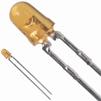
LED 3MM 585NM YELLOW TINT
Manufacturer
Avago Technologies US Inc.
Datasheet
1.HLMP-1521.pdf
(9 pages)
Specifications of HLMP-1421
Viewing Angle
45°
Package / Case
Radial - 2 Lead
Color
Yellow
Millicandela Rating
15mcd
Current - Test
10mA
Wavelength - Dominant
585nm
Wavelength - Peak
583nm
Voltage - Forward (vf) Typ
2V
Lens Type
Clear, Yellow Tinted
Lens Style/size
Round, 3mm, T-1
Height
4.70mm
Mounting Type
Through Hole
Resistance Tolerance
585nm
Led Size
T-1
Illumination Color
Yellow
Lens Color/style
Tinted Non-Diffused
Operating Voltage
2 V
Wavelength
585 nm
Luminous Intensity
15 mcd
Operating Current
10 mA
Lens Dimensions
3 mm
Lens Shape
Dome
Maximum Operating Temperature
+ 100 C
Minimum Operating Temperature
- 40 C
Mounting Style
Through Hole
Lead Free Status / RoHS Status
Lead free / RoHS Compliant
Luminous Flux @ Current - Test
-
Lead Free Status / Rohs Status
Lead free / RoHS Compliant
Other names
516-1296
Available stocks
Company
Part Number
Manufacturer
Quantity
Price
Company:

Part Number:
HLMP-1421
Manufacturer:
AVAGO
Quantity:
40 000
Company:
Part Number:
HLMP-1421
Manufacturer:
AVAGO
Quantity:
50 000
Company:
Part Number:
HLMP-1421-F0002
Manufacturer:
AVAGO
Quantity:
40 000
Company:
Part Number:
HLMP-1421-F0002
Manufacturer:
AVAGO
Quantity:
50 000
Company:
Part Number:
HLMP-1421-F00A2
Manufacturer:
AVAGO
Quantity:
50 000


90
80
70
60
50
40
30
20
10
0
1.0
90
80
70
60
50
40
30
20
10
0
1.0
4
Figure 1. Relative intensity vs. wavelength.
T-1 High Efficiency Red Non-Diffused
Figure 2. Forward current vs. forward voltage
characteristics.
Figure 5. Maximum tolerable peak current vs.
pulse duration. (I
V
2.0
F
90
80
70
60
50
40
30
20
10
– FORWARD VOLTAGE – V
0
1.0
6
5
4
3
2
1
1.0
V
2.0
F
6
5
4
3
2
1
– FORWARD VOLTAGE – V
1.0
3.0
V
2.0
F
t
– FORWARD VOLTAGE – V
p
3.0
10
– PULSE DURATION – µs
DC
t
p
4.0
10
MAX as per MAX ratings).
– PULSE DURATION – µs
3.0
4.0
100
5.0
100
4.0
5.0
1,000
1,000
5.0
10,000
10,000
Figure 3. Relative luminous intensity vs. DC
forward current.
Figure 6. Relative luminous intensity vs. angular displacement.
4.0
3.5
3.0
2.5
2.0
1.5
1.0
0.5
0
0
90°
80°
4.0
3.5
3.0
2.5
2.0
1.5
1.0
0.5
70°
0
90°
80°
0
I
60°
DC
70°
5
– DC CURRENT PER LED – mA
4.0
3.5
3.0
2.5
2.0
1.5
1.0
0.5
60°
50°
0
I
DC
0
5
10
50°
– DC CURRENT PER LED – mA
40°
I
10
DC
40°
5
15
– DC CURRENT PER LED – mA
30°
30°
10
15
20
20°
20°
20
15
25
10°
10°
20
25
30
0°
0°
NON-DIFFUSED
1.0
30
.8
.6
.4
.2
25
0°
0°
1.0
NON-DIFFUSED
.8
.6
.4
.2
20°
30
Figure 4. Relative efficiency (luminous intensity
per unit current) vs. peak LED current.
20°
40°
1.6
1.5
1.4
1.3
1.2
1.1
1.0
0.9
0.8
0.7
0
40°
1.6
1.5
1.4
1.3
1.2
1.1
1.0
0.9
0.8
0.7
I
10
60°
PEAK
0
60°
20
– PEAK CURRENT PER LED – mA
1.6
1.5
1.4
1.3
1.2
1.1
1.0
0.9
0.8
0.7
I
10
PEAK
0
80°
30
20
– PEAK CURRENT PER LED – mA
I
10
80°
PEAK
40
30
100°
20
– PEAK CURRENT PER LED – mA
50
40
100°
30
60
50
40
70
60
50
80
70
60
90
80
70
90
80
90
Related parts for HLMP-1421
Image
Part Number
Description
Manufacturer
Datasheet
Request
R

Part Number:
Description:
LED 3MM 569NM GREEN DIFF
Manufacturer:
Avago Technologies US Inc.
Datasheet:

Part Number:
Description:
LED 5MM 639NM RED WATER CLEAR
Manufacturer:
Avago Technologies US Inc.
Datasheet:

Part Number:
Description:
LED 5MM 635NM HE RED WATER CLEAR
Manufacturer:
Avago Technologies US Inc.
Datasheet:

Part Number:
Description:
LED Lamp
Manufacturer:
Avago Technologies US Inc.
Datasheet:
Part Number:
Description:
LED, T-1 3/4, RED, 8.6MCD, 626NM
Manufacturer:
Avago Technologies US Inc.
Datasheet:

Part Number:
Description:
LED 5MM FLAT TOP INGAN WHITE
Manufacturer:
Avago Technologies US Inc.
Datasheet:
Part Number:
Description:
LED 5MM FLAT TOP INGAN WHITE
Manufacturer:
Avago Technologies US Inc.
Datasheet:
Part Number:
Description:
LED 5MM FLAT TOP INGAN WHITE
Manufacturer:
Avago Technologies US Inc.
Datasheet:
Part Number:
Description:
LED 5MM FLAT TOP INGAN WHITE
Manufacturer:
Avago Technologies US Inc.
Datasheet:

Part Number:
Description:
GREEN T-1 LED MAX 34MCD
Manufacturer:
Avago Technologies US Inc.
Datasheet:

Part Number:
Description:
LED T 1 3/4 OR 5MM AMBER
Manufacturer:
Avago Technologies US Inc.
Datasheet:
Part Number:
Description:
YELLOW T-1 LED MAX 75MCD
Manufacturer:
Avago Technologies US Inc.
Datasheet:
Part Number:
Description:
LED, T-1 3/4, BLUE, 1500MCD, 470NM
Manufacturer:
Avago Technologies US Inc.
Datasheet:
Part Number:
Description:
LED, T-1 3/4, BLUE, 5500MCD, 470NM
Manufacturer:
Avago Technologies US Inc.
Datasheet:
Part Number:
Description:
LED, T-1 3/4, RED, 2.1MCD, 626NM
Manufacturer:
Avago Technologies US Inc.
Datasheet: