HLMP-1540-IJ000 Avago Technologies US Inc., HLMP-1540-IJ000 Datasheet - Page 4
HLMP-1540-IJ000
Manufacturer Part Number
HLMP-1540-IJ000
Description
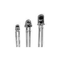
LED 3MM GAP NON-DIFFUSED GREEN
Manufacturer
Avago Technologies US Inc.
Type
Uni-Colorr
Datasheet
1.HLMP-1340.pdf
(12 pages)
Specifications of HLMP-1540-IJ000
Viewing Angle
45°
Package / Case
Radial - 2 Lead
Color
Green
Millicandela Rating
60mcd
Current - Test
20mA
Wavelength - Dominant
569nm
Wavelength - Peak
565nm
Voltage - Forward (vf) Typ
2.2V
Lens Type
Clear
Lens Style/size
Round, 3mm, T-1
Height
4.70mm
Mounting Type
Through Hole
Resistance Tolerance
569nm
Led Size
T-1
Illumination Color
Green
Wavelength
569 nm
Mounting Style
Through Hole
Package Type
T-1
Emitting Color
Yellow Green
Luminous Intensity
60mcd
Test Current (it)
20mA
Forward Current
25mA
Dominant Wave Length
569nm
Forward Voltage
3V
Product Length (mm)
3.43mm
Product Height (mm)
4.7mm
Product Depth (mm)
3.43mm
Mounting
Through Hole
Peak Wavelength
565nm
Shape Type
Circular
Chip Material
GaP
Main Category
Standard LED
Number Of Elements
1
Pin Count
2
Operating Temperature Classification
Commercial
Operating Temp Range
-20C to 100C
Reverse Voltage
5V
Lens Dimensions
3.18x3.18x3.68mm
Lead Free Status / RoHS Status
Not applicable / Not applicable
Luminous Flux @ Current - Test
-
Lead Free Status / Rohs Status
Compliant
Available stocks
Company
Part Number
Manufacturer
Quantity
Price
Company:

Part Number:
HLMP-1540-IJ000
Manufacturer:
AVAGO
Quantity:
40 000
Company:
Part Number:
HLMP-1540-IJ000
Manufacturer:
AVAGO
Quantity:
50 000


Part Numbering System
4
HLMP - x x xx - x x x xx
Absolute Maximum Ratings at T
Parameter
Peak Forward Current
Average Forward Current
DC Current
Transient Forward Current
(10 μs Pulse)
Reverse Voltage (I
LED Junction Temperature
Operating Temperature Range
Storage Temperature Range
Notes:
1. See Figure 2 to establish pulsed operating conditions.
2. For Red and Green series derate linearly from 50°C at 0.5 mA/°C. For Yellow series derate linearly from 50°C at 0.2 mA/°C.
3. The transient peak current is the maximum non-recurring peak current the devices can withstand without damaging the LED die and wire bonds.
It is not recommended that the device be operated at peak currents beyond the Absolute Maximum Peak Forward Current.
[2]
R
= 100 μA)
[1]
[3]
A
= 25°C
Mechanical Options
00: Bulk
01: Tape & Reel, Crimped Leads
02, Bx: Tape & Reel, Straight Leads
A1, B1: Right Angle Housing, Uneven Leads
A2, B2: Right Angle Housing, Even Leads
Dx, Ex: Ammo Pack, Straight Leads
FH: 2 Iv Bin Select with Inventory Control
Vx: Ammo Pack, Crimped Leads
Color Bin Options
0: Full Color Bin Distribution
N: Color Bin 6 & 7 Only
Maximum Iv Bin Options
0: Open (No. Max. Limit)
Others: Please Refer to the Iv Bin Table
Minimum Iv Bin Options
Please Refer to the Iv Bin Table
Color Options
3, 7: GaP HER
4, 8: GaP Yellow (except K4xx series)
5, 9: GaP Green
6: GaP Emerald Green
Package Option
1, K: T-1 (3 mm)
3: T-1
Red
90
25
30
500
5
110
-40 to +100
-40 to +100
3
/
4
(5 mm)
Yellow
60
20
20
500
5
110
-40 to +100
-40 to +100
Green/Emerald Green
90
25
30
500
5
110
-20 to +100
-40 to +100
Units
mA
mA
mA
mA
V
°C
°C
°C
Related parts for HLMP-1540-IJ000
Image
Part Number
Description
Manufacturer
Datasheet
Request
R

Part Number:
Description:
General Purpose Visible Dome-Style LED,Green,Clear,LED-2b
Manufacturer:
Avago Technologies US Inc.
Datasheet:

Part Number:
Description:
LED 3MM 569NM GREEN WATER CLEAR
Manufacturer:
Avago Technologies US Inc.
Datasheet:

Part Number:
Description:
LED 3MM GAP GREEN STR LEADS
Manufacturer:
Avago Technologies US Inc.
Datasheet:

Part Number:
Description:
LED 3MM GAP GREEN CRIMPED LEADS
Manufacturer:
Avago Technologies US Inc.
Datasheet:

Part Number:
Description:
LED 3MM 569NM GREEN DIFF
Manufacturer:
Avago Technologies US Inc.
Datasheet:

Part Number:
Description:
LED 5MM 639NM RED WATER CLEAR
Manufacturer:
Avago Technologies US Inc.
Datasheet:

Part Number:
Description:
LED 5MM 635NM HE RED WATER CLEAR
Manufacturer:
Avago Technologies US Inc.
Datasheet:
Part Number:
Description:
LED Lamp
Manufacturer:
Avago Technologies US Inc.
Datasheet:

Part Number:
Description:
LED 5MM FLAT TOP INGAN WHITE
Manufacturer:
Avago Technologies US Inc.
Datasheet:
Part Number:
Description:
LED 5MM FLAT TOP INGAN WHITE
Manufacturer:
Avago Technologies US Inc.
Datasheet:
Part Number:
Description:
LED 5MM FLAT TOP INGAN WHITE
Manufacturer:
Avago Technologies US Inc.
Datasheet:
Part Number:
Description:
LED 5MM FLAT TOP INGAN WHITE
Manufacturer:
Avago Technologies US Inc.
Datasheet:
Part Number:
Description:
GREEN T-1 LED MAX 34MCD
Manufacturer:
Avago Technologies US Inc.
Datasheet:

Part Number:
Description:
LED T 1 3/4 OR 5MM AMBER
Manufacturer:
Avago Technologies US Inc.
Datasheet:
Part Number:
Description:
YELLOW T-1 LED MAX 75MCD
Manufacturer:
Avago Technologies US Inc.
Datasheet: