HLMP-3850 Avago Technologies US Inc., HLMP-3850 Datasheet - Page 5
HLMP-3850
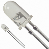
Manufacturer Part Number
HLMP-3850
Description
LED 5MM 583NM YELLOW WATER CLEAR
Manufacturer
Avago Technologies US Inc.
Type
Uni-Colorr
Datasheet
1.HLMP-1340.pdf
(12 pages)
Specifications of HLMP-3850
Viewing Angle
24°
Package / Case
Radial - 2 Lead
Color
Yellow
Millicandela Rating
140mcd
Current - Test
20mA
Wavelength - Dominant
585nm
Wavelength - Peak
583nm
Voltage - Forward (vf) Typ
2.1V
Lens Type
Clear
Lens Style/size
Round, 5mm, T-1 3/4
Height
8.81mm
Mounting Type
Through Hole
Resistance Tolerance
585nm
Led Size
T-1 3/4
Illumination Color
Yellow
Lens Color/style
Tinted Diffused
Operating Voltage
2.1 V
Wavelength
585 nm
Luminous Intensity
140 mcd
Operating Current
20 mA
Lens Dimensions
5 mm
Lens Shape
Dome
Maximum Operating Temperature
+ 100 C
Minimum Operating Temperature
- 40 C
Mounting Style
Through Hole
Package Type
T-1 3/4
Emitting Color
Amber
Test Current (it)
20mA
Forward Current
20mA
Dominant Wave Length
585nm
Forward Voltage
2.6V
Product Length (mm)
6.1mm
Product Height (mm)
9.19mm
Product Depth (mm)
6.1mm
Mounting
Through Hole
Peak Wavelength
583nm
Shape Type
Circular
Chip Material
GaP
Main Category
Standard LED
Number Of Elements
1
Pin Count
2
Operating Temperature Classification
Industrial
Operating Temp Range
-40C to 100C
Reverse Voltage
5V
Lead Free Status / RoHS Status
Lead free / RoHS Compliant
Luminous Flux @ Current - Test
-
Lead Free Status / Rohs Status
Lead free / RoHS Compliant
Other names
516-1346
Available stocks
Company
Part Number
Manufacturer
Quantity
Price
Company:

Part Number:
HLMP-3850
Manufacturer:
AVAGO
Quantity:
50 000
Company:
Part Number:
HLMP-3850-K0002
Manufacturer:
AVAGO
Quantity:
40 000
Company:
Part Number:
HLMP-3850-K0002
Manufacturer:
AVAGO
Quantity:
50 000
Company:
Part Number:
HLMP-3850-K00B2
Manufacturer:
AVAGO
Quantity:
40 000
Company:
Part Number:
HLMP-3850-K00B2
Manufacturer:
AVAGO
Quantity:
50 000


Electrical/Optical Characteristics at T
Symbol
O
O
'O
W
C
RT
V
V
K
Notes:
1. The dominant wavelength, Od, is derived from the CIE chromaticity diagram and represents the single wavelength which defines the color of the
2. The radiant intensity, Ie, in watts per steradian, may be found from the equation Ie = IV/K
5
s
PEAK
d
F
R
v
J-PIN
device.
the luminous efficacy in lumens/watt.
3
/
4
Description
Peak
Wavelength
Dominant
Wavelength
Spectral Line
Halfwidth
Speed of
Respond
Capacitance
Thermal
Resistance
Forward
Voltage
Reverse
Breakdown
Voltage
Luminous
Efficacy
T-1
37xx
38xx
39xx
37xx
38xx
39xx
37xx
38xx
39xx
37xx
38xx
39xx
37xx
38xx
39xx
37xx
38xx
39xx
37xx
38xx
39xx
37xx
38xx
39xx
37xx
38xx
39xx
3
/
4
A
= 25°C
T-1
Low Dome
3390
3490
3590
3390
3490
3590
3390
3490
3590
3390
3490
3590
3390
3490
3590
3390
3490
3590
3390
3490
3590
3390
3490
3590
3390
3490
3590
3
/
4
T-1
1340
1440
1540
K640
1340
1440
1540
K640
1340
1440
1540
K640
1340
1440
1540
K640
1340
1440
1540
K640
1340
1440
1540
K640
1340
1440
1540
K640
1340
1440
1540
K640
1340
1440
1540
K640
Min.
1.5
1.5
1.5
5.0
V
, where IV is the luminous intensity in candelas and K
Typ.
635
583
565
558
626
585
569
560
40
36
28
24
90
90
500
3100
11
15
18
35
210
210
210
510
290
290
290
290
1.9
2.1
2.2
2.2
145
500
595
655
Max.
2.6
2.6
3.0
3.0
Units
nm
nm
nm
ns
pF
°C/W
V
V
lumens
watt
Conditions
Test
Measurement
at Peak
Note 1
V
f = 1 MHz
Junction to
Cathode Lead
I
(Figure 3)
I
Note 2
F
F
F
= 100 μA
= 20 mA
= 0,
V
is
Related parts for HLMP-3850
Image
Part Number
Description
Manufacturer
Datasheet
Request
R

Part Number:
Description:
LED 5MM 639NM RED WATER CLEAR
Manufacturer:
Avago Technologies US Inc.
Datasheet:

Part Number:
Description:
LED 5MM 635NM HE RED WATER CLEAR
Manufacturer:
Avago Technologies US Inc.
Datasheet:

Part Number:
Description:
LED 3MM 569NM GREEN DIFF
Manufacturer:
Avago Technologies US Inc.
Datasheet:

Part Number:
Description:
LED LT BAR 19.05X3.81MM SGL YLW
Manufacturer:
Avago Technologies US Inc.
Datasheet:

Part Number:
Description:
LED Lamp
Manufacturer:
Avago Technologies US Inc.
Datasheet:

Part Number:
Description:
LED 5MM ALINGAP 590NM AMB 15DEG
Manufacturer:
Avago Technologies US Inc.
Datasheet:

Part Number:
Description:
LED T1 3/4 5MM WHT PREC OPT PREF
Manufacturer:
Avago Technologies US Inc.
Datasheet:
Part Number:
Description:
LED, T-1 3/4, RED, 8.6MCD, 626NM
Manufacturer:
Avago Technologies US Inc.
Datasheet:

Part Number:
Description:
LED 5MM FLAT TOP INGAN WHITE
Manufacturer:
Avago Technologies US Inc.
Datasheet:
Part Number:
Description:
LED 5MM FLAT TOP INGAN WHITE
Manufacturer:
Avago Technologies US Inc.
Datasheet:
Part Number:
Description:
LED 5MM FLAT TOP INGAN WHITE
Manufacturer:
Avago Technologies US Inc.
Datasheet:
Part Number:
Description:
LED 5MM FLAT TOP INGAN WHITE
Manufacturer:
Avago Technologies US Inc.
Datasheet:

Part Number:
Description:
LED
Manufacturer:
Avago Technologies US Inc.
Datasheet:

Part Number:
Description:
LED T 1 3/4 OR 5MM AMBER
Manufacturer:
Avago Technologies US Inc.
Datasheet:

Part Number:
Description:
LED T1-3/4 SUPER BRIGHT GREEN
Manufacturer:
Avago Technologies US Inc.