HSMF-C113 Avago Technologies US Inc., HSMF-C113 Datasheet - Page 6
HSMF-C113
Manufacturer Part Number
HSMF-C113
Description
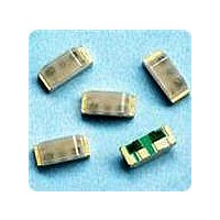
LED CHIP RGB 2.5X1.0X1.0MM SMD
Manufacturer
Avago Technologies US Inc.
Type
Tri-Colorr
Datasheet
1.HSMF-C113.pdf
(8 pages)
Specifications of HSMF-C113
Viewing Angle
120° Red, 125° Green, 125° Blue
Package / Case
4-SMD, No Leads
Mounting Type
Surface Mount, Right Angle
Color
Red, Green, Blue (RGB)
Lens Style/size
Rectangle, 2.1mm x 1mm
Voltage - Forward (vf) Typ
1.9V Red, 2.0V Green, 3.4V Blue
Millicandela Rating
80mcd Red, 50mcd Green, 60mcd Blue
Luminous Flux @ Current - Test
251 mlm Red, 169 mlm Green, 203 mlm Blue
Current - Test
20mA
Lens Type
Diffused
Wavelength - Peak
637nm, 570nm, 468nm
Resistance Tolerance
626nm, 572nm, 470nm
Led Size
2.5 mm x 1 mm
Illumination Color
Red, Green, Blue
Lens Color/style
Diffused
Operating Voltage
1.9 V, 2 V, 3.4 V
Wavelength
626 nm, 572 nm, 470 nm
Luminous Intensity
80 mcd, 50 mcd, 60 mcd
Mounting Style
SMD/SMT
Operating Current
20 mA
Lens Dimensions
2.1 mm x 1 mm
Lens Shape
Rectangular
Maximum Operating Temperature
+ 85 C
Minimum Operating Temperature
- 40 C
Peak Wavelength
637 nm, 670 nm, 468 nm
Package Type
Chip Led
Emitting Color
Blue/Yellow Green/Red
Test Current (it)
20mA
Forward Current
20mA
Dominant Wave Length
470/572/626nm
Forward Voltage
3.9/2.6/2V
Product Length (mm)
2.5mm
Product Height (mm)
1mm
Product Depth (mm)
1mm
Mounting
Surface Mount
Shape Type
Rectangular
Chip Material
InGaN/AlGaInP/AlGaInP
Main Category
Chip LED
Number Of Elements
3
Pin Count
4
Operating Temperature Classification
Industrial
Operating Temp Range
-40C to 85C
Reverse Voltage
5V
Power Dissipation
59/39/36mW
Lead Free Status / RoHS Status
Lead free / RoHS Compliant
Lead Free Status / RoHS Status
Lead free / RoHS Compliant, Lead free / RoHS Compliant
Available stocks
Company
Part Number
Manufacturer
Quantity
Price
Company:

Part Number:
HSMF-C113
Manufacturer:
MURATA
Quantity:
30
Company:
Part Number:
HSMF-C113
Manufacturer:
AVAGO
Quantity:
50 000


Figure 6. Recommended reflow soldering profile.
Figure 8. Recommended soldering land pattern.
Notes:
1. All dimensions are in millimeters (inches).
2. Tolerance is ±0.1mm (±0.004in.) unless otherwise specified.
Figure 9. Reeling orientation.
6
0.50
PRINTED LABEL
140-160˚C
OVER 2 MIN.
4˚C/SEC.
10 SEC. MAX.
MAX.
230˚C MAX.
USER FEED DIRECTION
1.80
0.4
TIME
0.45
0.85
4˚C/SEC. MAX.
0.10
-3˚C/SEC.
0.90
CATHODE SIDE
Figure 7. Recommended Pb-free reflow soldering profile.
217 °C
200 °C
150 °C
3 °C/SEC. MAX.
3 °C/SEC. MAX.
60 - 120 SEC.
255 - 260 °C
TIME
EMITTING DIRECTION
(Acc. to J-STD-020C)
10 - 30 SEC.
100 SEC. MAX.
6 °C/SEC. MAX.
Related parts for HSMF-C113
Image
Part Number
Description
Manufacturer
Datasheet
Request
R

Part Number:
Description:
LED CHIP GAP GREEN/YELLOW SMD
Manufacturer:
Avago Technologies US Inc.
Datasheet:

Part Number:
Description:
LED BICOLOR YLW/GN DIFF 1210 SMD
Manufacturer:
Avago Technologies US Inc.
Datasheet:

Part Number:
Description:
LED CHIP GRN/ORN 3.2X2.7MM SMD
Manufacturer:
Avago Technologies US Inc.
Datasheet:

Part Number:
Description:
LED IND RED/GRN TOP MOUNT 4PLCC
Manufacturer:
Avago Technologies US Inc.
Datasheet:
Part Number:
Description:
LED IND YLW/YGRN TOP MOUNT 4PLCC
Manufacturer:
Avago Technologies US Inc.
Datasheet:

Part Number:
Description:
LED CHIPLED AMB/BLUE DIFF 0603
Manufacturer:
Avago Technologies US Inc.
Datasheet:
Part Number:
Description:
LED CHIPLED RED/GRN DIFF 0603
Manufacturer:
Avago Technologies US Inc.
Datasheet:
Part Number:
Description:
LED RED/GREEN/BLUE 40MCD 5V SMD
Manufacturer:
Avago Technologies US Inc.
Datasheet:
Part Number:
Description:
Standard LED - SMD Red/YGrn/Blue Tri-Color
Manufacturer:
Avago Technologies US Inc.
Datasheet:

Part Number:
Description:
LED CHIP RGB 3.2X2.7X1.1MM SMD
Manufacturer:
Avago Technologies US Inc.
Datasheet:

Part Number:
Description:
LED BICOLOR GN/HER DIFF 1210 SMD
Manufacturer:
Avago Technologies US Inc.
Datasheet:

Part Number:
Description:
LED BICOLOR HER/GN DIFF 0603 SMD
Manufacturer:
Avago Technologies US Inc.
Datasheet:
Part Number:
Description:
LED IND RED/YLW TOP MOUNT 4PLCC
Manufacturer:
Avago Technologies US Inc.
Datasheet:
Part Number:
Description:
LED IND RED/EGRN TOP MOUNT 4PLCC
Manufacturer:
Avago Technologies US Inc.
Datasheet:
Part Number:
Description:
LED IND ORN/YGRN TOP MOUNT 4PLCC
Manufacturer:
Avago Technologies US Inc.
Datasheet: