HSMF-C169 Avago Technologies US Inc., HSMF-C169 Datasheet - Page 3
HSMF-C169
Manufacturer Part Number
HSMF-C169
Description
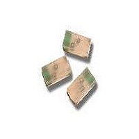
LED CHIPLED AMB/BLUE DIFF 0603
Manufacturer
Avago Technologies US Inc.
Specifications of HSMF-C169
Package / Case
0603 (1608 Metric)
Viewing Angle
120°
Color
Amber, Blue
Millicandela Rating
90mcd Amber, 10mcd Blue
Current - Test
20mA
Wavelength - Dominant
592nm, 470nm
Wavelength - Peak
595nm, 468nm
Voltage - Forward (vf) Typ
1.9V Amber, 3.4V Blue
Lens Type
Diffused
Lens Style/size
Rectangle, 1.6mm x 0.8mm
Size / Dimension
1.60mm L x 0.80mm W
Height
0.50mm
Mounting Type
Surface Mount
Resistance Tolerance
592nm, 470nm
Led Size
0603
Illumination Color
Amber, Blue
Lens Color/style
Diffused
Operating Voltage
1.9 V, 3.4 V
Wavelength
592 nm, 470 nm
Luminous Intensity
90 mcd, 10 mcd
Mounting Style
SMD/SMT
Operating Current
20 mA
Lens Dimensions
1.6 mm x 0.8 mm
Lens Shape
Rectangular
Maximum Operating Temperature
+ 85 C
Minimum Operating Temperature
- 40 C
Peak Wavelength
595 nm, 468 nm
Lead Free Status / RoHS Status
Lead free / RoHS Compliant
Luminous Flux @ Current - Test
-
Lead Free Status / Rohs Status
Lead free / RoHS Compliant
Available stocks
Company
Part Number
Manufacturer
Quantity
Price
Company:

Part Number:
HSMF-C169
Manufacturer:
AVAGO
Quantity:
50 000


Electrical Characteristics at T
Color
AlInGaP Red
AlInGaP Amber
AlInGaP Red
AlInGaP Amber
InGaN Green
InGaN Blue
HER
GaP Orange
GaP Yellow
GaP Green
Notes:
1. V
2. The product testing is based on 20 mA. This is for reference only.
Optical Characteristics at T
Color
AlInGaP Red
AlInGaP Amber
AlInGaP Red
AlInGaP Amber
InGaN Green
InGaN Blue
HER
GaP Orange
GaP Yellow
GaP Green
Notes:
1. The luminous intensity I
2. The dominant wavelength O
3. T
4. The product testing is based on 20 mA. This is for reference purpose.
3
package.
F
1/2
Tolerance: ± 0.1 V.
is the off-axis angle where the luminous intensity is 1/2 the peak intensity.
[2]
[4]
[2]
[4]
Luminous Intensity
I
20 mA
20 mA
10 mA
10 mA
10 mA
10 mA
20 mA
20 mA
20 mA
20 mA
v
v
A
(mcd) @ I
is measured at the peak of the spatial radiation pattern which may not be aligned with the mechanical axis of the lamp
= 25˚C
A
= 25˚C
d
Forward Voltage
V
20 mA
20 mA
10 mA
10 mA
10 mA
10 mA
20 mA
20 mA
20 mA
20 mA
is derived from the CIE Chromatically Diagram and represents the perceived color of the device.
F
(Volts) @ I
F [1]
Min.
28.5
28.5
11.2
11.2
18
2.8
2.8
2.8
2.8
4.5
F [1]
Typ.
1.9
1.9
1.8
1.8
3.4
3.4
2.1
2.2
2.1
2.2
Typ.
90
90
35
35
45
10
10
8
8
15
Max.
2.4
2.4
2.3
2.3
3.8
3.8
2.6
2.6
2.6
2.6
Peak
Wavelength
O
Typ.
637
595
637
595
523
468
636
605
589
570
peak
(nm)
Reverse
Breakdown
V
@ I
Min.
5
5
5
5
5
5
5
5
5
5
R
(Volts)
R
= 100 μA
Color
Dominant
Wavelength
O
Typ.
626
592
626
592
525
470
621
604
586
572
d [2]
(nm)
Capacitance
C (pF), @ V
f = 1 MHz
Typ.
15
11
15
11
35
35
5
7
6
9
Viewing Angle
2 T
Typ.
120
120
120
120
120
120
120
120
120
120
1/2
Degrees
F
= 0,
[3]
Luminous
Efficacy
K
Typ.
155
480
155
480
500
80
145
500
595
380
Thermal
Resistance
RT
Typ.
300
300
300
300
500
500
325
325
325
325
v
J-PIN
(lm/W)
(˚C/W)
Related parts for HSMF-C169
Image
Part Number
Description
Manufacturer
Datasheet
Request
R

Part Number:
Description:
LED CHIP GAP GREEN/YELLOW SMD
Manufacturer:
Avago Technologies US Inc.
Datasheet:

Part Number:
Description:
LED BICOLOR YLW/GN DIFF 1210 SMD
Manufacturer:
Avago Technologies US Inc.
Datasheet:

Part Number:
Description:
LED CHIP GRN/ORN 3.2X2.7MM SMD
Manufacturer:
Avago Technologies US Inc.
Datasheet:

Part Number:
Description:
LED IND RED/GRN TOP MOUNT 4PLCC
Manufacturer:
Avago Technologies US Inc.
Datasheet:
Part Number:
Description:
LED IND YLW/YGRN TOP MOUNT 4PLCC
Manufacturer:
Avago Technologies US Inc.
Datasheet:
Part Number:
Description:
LED CHIP RGB 2.5X1.0X1.0MM SMD
Manufacturer:
Avago Technologies US Inc.
Datasheet:

Part Number:
Description:
LED CHIPLED RED/GRN DIFF 0603
Manufacturer:
Avago Technologies US Inc.
Datasheet:
Part Number:
Description:
LED RED/GREEN/BLUE 40MCD 5V SMD
Manufacturer:
Avago Technologies US Inc.
Datasheet:
Part Number:
Description:
Standard LED - SMD Red/YGrn/Blue Tri-Color
Manufacturer:
Avago Technologies US Inc.
Datasheet:

Part Number:
Description:
LED CHIP RGB 3.2X2.7X1.1MM SMD
Manufacturer:
Avago Technologies US Inc.
Datasheet:

Part Number:
Description:
LED BICOLOR GN/HER DIFF 1210 SMD
Manufacturer:
Avago Technologies US Inc.
Datasheet:

Part Number:
Description:
LED BICOLOR HER/GN DIFF 0603 SMD
Manufacturer:
Avago Technologies US Inc.
Datasheet:
Part Number:
Description:
LED IND RED/YLW TOP MOUNT 4PLCC
Manufacturer:
Avago Technologies US Inc.
Datasheet:
Part Number:
Description:
LED IND RED/EGRN TOP MOUNT 4PLCC
Manufacturer:
Avago Technologies US Inc.
Datasheet:
Part Number:
Description:
LED IND ORN/YGRN TOP MOUNT 4PLCC
Manufacturer:
Avago Technologies US Inc.
Datasheet: