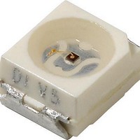
TLMG3100-GS08 Vishay, TLMG3100-GS08 Datasheet

TLMG3100-GS08
Specifications of TLMG3100-GS08
Available stocks
Related parts for TLMG3100-GS08
TLMG3100-GS08 Summary of contents
Page 1
... Product series: standard • Angle of half intensity: ± 60° PARTS TABLE PART TLMH3100 TLMH3101 TLMH3102 TLMO3100 TLMO3101 TLMY3100 TLMY3102 TLMG3100 TLMG3102 TLMG3105 TLMP3100 TLMP3101 TLMP3107 TLMP3102 Document Number 83032 Rev. 1.8, 12-Sep-07 Standard SMD LED PLCC-2 FEATURES • SMD LEDs with exceptional brightness • ...
Page 2
... TLMG/H/O/P/Y310. Vishay Semiconductors ABSOLUTE MAXIMUM RATINGS PARAMETER Reverse voltage DC forward current Surge forward current Power dissipation Junction temperature Operating temperature range Storage temperature range Soldering temperature Thermal resistance junction/ ambient Note °C, unless otherwise specified amb OPTICAL AND ELECTRICAL CHARACTERISTICS PARAMETER ...
Page 3
... In one packing unit I /I Vmax Vmin Document Number 83032 Rev. 1.8, 12-Sep-07 1) TLMY310., YELLOW PART SYMBOL TLMY3100 TLMY3102 I V λ λ ϕ µ MHz TLMG310., GREEN PART SYMBOL I TLMG3100 TLMG3102 TLMG3105 V λ λ ϕ µ MHz TLMP310., PURE GREEN PART SYMBOL I TLMP3100 V I TLMP3101 ...
Page 4
... TLMG/H/O/P/Y310. Vishay Semiconductors TYPICAL CHARACTERISTICS °C, unless otherwise specified amb 125 100 Ambient Temperature (°C) 95 10904 amb Figure 1. Power Dissipation vs. Ambient Temperature Ambient Temperature (°C) 95 10905 amb Figure 2. Forward Current vs. Ambient Temperature for InGaN 10000 0.005 amb p 0.01 1000 0.02 100 ...
Page 5
... F 0. 9990 P Figure 10. Forward Current vs. Forward Voltage 100 95 9994 Figure 11. Rel. Luminous Intensity vs. Ambient Temperature 690 670 95 10259 Figure 12. Rel. Lumin. Intensity vs. Forw. Current/Duty Cycle TLMG/H/O/P/Y310. Vishay Semiconductors 100 soft orange Forward Voltage (V) F 2.0 soft orange 1.6 1 ...
Page 6
... TLMG/H/O/P/Y310. Vishay Semiconductors 10 soft orange 1 0.1 0. Forward Current (mA) 95 9997 F Figure 13. Relative Luminous Intensity vs. Forward Current 1.2 soft orange 1.0 0.8 0.6 0.4 0.2 0 570 590 610 630 λ - Wavelength (nm) 95 10324 Figure 14. Relative Intensity vs. Wavelength 100 yellow Forward Voltage (V) ...
Page 7
... Figure 21. Rel. Luminous Intensity vs. Ambient Temperature Document Number 83032 Rev. 1.8, 12-Sep-07 650 630 95 10263 Figure 22. Specific Luminous Intensity vs. Forward Current 9996 Figure 23. Relative Luminous Intensity vs. Forward Current 80 100 95 10038 TLMG/H/O/P/Y310. Vishay Semiconductors 2.4 green 2.0 1.6 1.2 0.8 0 100 200 ...
Page 8
... TLMG/H/O/P/Y310. Vishay Semiconductors 100 pure green Forward Voltage (V) 95 9988 F Figure 25. Forward Current vs. Forward Voltage 2.0 pure green 1.6 1.2 0.8 0 Ambient Temperature (°C) 95 9991 am b Figure 26. Rel. Luminous Intensity vs. Ambient Temperature 2.4 pure green 2.0 1.6 1.2 0.8 0.4 ...
Page 9
... PACKAGE DIMENSIONS in millimeters 3.5 ± 0.2 Pin identification C 2 0.15 3 Drawing-No.: 6.541-5025.01-4 Issue: 8; 22.11.05 95 11314-1 Document Number 83032 Rev. 1.8, 12-Sep-07 technical drawings according to DIN specifications Mounting Pad Layout A 1.6 (1.9) TLMG/H/O/P/Y310. Vishay Semiconductors 1.2 area covered with solder resist 4 www.vishay.com 9 ...
Page 10
... Various national and international initiatives are pressing for an earlier ban on these substances. Vishay Semiconductor GmbH has been able to use its policy of continuous improvements to eliminate the use of ODSs listed in the following documents. 1. Annex A, B and list of transitional substances of the Montreal Protocol and the London Amendments respectively 2 ...
Page 11
... Vishay disclaims any and all liability arising out of the use or application of any product described herein or of any information provided herein to the maximum extent permitted by law. The product specifications do not expand or otherwise modify Vishay’ ...


