LY E63B-CBEA-26-1 OSRAM Opto Semiconductors Inc, LY E63B-CBEA-26-1 Datasheet
LY E63B-CBEA-26-1
Specifications of LY E63B-CBEA-26-1
LYE63BCBEA261
Q65110A0091


Related parts for LY E63B-CBEA-26-1


LY E63B-CBEA-26-1 Summary of contents
Page 1
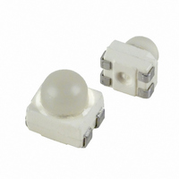
... Power TOPLED with Lens Enhanced optical Power LED (HOP2000) LS E63B, LA E63B, LO E63B, LY E63B Vorläufige Daten / Preliminary Data Besondere Merkmale • Gehäusetyp: weißes P-LCC-4-Gehäuse • Besonderheit des Bauteils: fokussierte Abstrahlung in SMT-Technologie; hohe Helligkeit in Achsrichtung • Wellenlänge: 633 nm (super-rot), 617 nm (amber), 606 nm (orange), 587 nm (gelb) • ...
Page 2
... Emission LS E63B-BBCB-1-1 super-red LA E63B-CBEA-24-1 amber LO E63B-CBEA-24-1 orange LY E63B-CBEA-26-1 yellow Anm.: -1-1 gesamter Farbbereich (siehe Seite 4) -24-1 gesamter Farbbereich, Lieferung in Einzelgruppen (siehe Seite 5) -26-1 gesamter Farbbereich, Lieferung in Einzelgruppen (siehe Seite 5) -24-1 gesamter Durchlassspannungsbereich, Lieferung in Einzelgruppen (siehe Seite 5) -26-1 gesamter Durchlassspannungsbereich, Lieferung in Einzelgruppen (siehe Seite 5) Die Standardlieferform von Serientypen beinhaltet eine Familiengruppe, die aus nur 4 Halbgruppen besteht. Einzelne Halbgruppen sind nicht erhä ...
Page 3
... A Wärmewiderstand Thermal resistance Sperrschicht/Umgebung Junction/ambient Sperrschicht/Lötpad Junction/soldering point Montage auf PC-Board FR 4 (Padgröß mounted on PC board FR 4 (pad size 1) für kurzzeitigen Betrieb geeignet / suitable for short term application 2003-06-02 LS E63B, LA E63B, LO E63B, LY E63B Symbol Symbol stg ...
Page 4
... Wavelengths are tested at a current pulse duration and a tolerance of ±1 nm. 2) Durchlassspannungsgruppen werden mit einer Stromeinprägedauer von 1 ms und einer Genauigkeit von ±0,05 V ermittelt. Forward voltage groups are tested at a current pulse duration and a tolerance of ±0.05 V. 2003-06-02 LS E63B, LA E63B, LO E63B, LY E63B Symbol Symbol (typ.) peak (typ ...
Page 5
... Durchlassspannungsgruppen für super-rot / orange / gelb Forward voltage groups for super-red / orange / yellow Gruppe Durchlassspannung Group Forward voltage min. max. 3 1.9 2.2 4 2.2 2.5 2003-06-02 LS E63B, LA E63B, LO E63B, LY E63B orange yellow Einheit Unit max. min. max. 603 580 583 nm 606 583 586 nm 609 ...
Page 6
... Luminous intensity is tested at a current pulse duration and a tolerance of ±11 %. Gruppenbezeichnung auf Etikett Group Name on Label Beispiel: DA-2-3A Example: DA-2-3A Partieller Lichtfluss Partial Flux Group D 2003-06-02 LS E63B, LA E63B, LO E63B, LY E63B Partieller Lichtfluss Lichtstärke Partial Flux Luminous Intensity E I [lux] [mcd] ...
Page 7
... Prinzipieller Meßaufbau für partial flux Messung Schematic Test Methode for partial flux measurement 2003-06-02 LS E63B, LA E63B, LO E63B, LY E63B Referenzebene des Detektors (ø14 mm) Reference layer of detector (ø14 mm) = 40˚ 7 OHAY0907 ...
Page 8
... Standard eye response curve 100 % I rel 400 450 I Abstrahlcharakteristik rel Radiation Characteristic 40˚ 30˚ 50˚ 60˚ 70˚ 80˚ 90˚ 100˚ 1.0 0.8 2003-06-02 LS E63B, LA E63B, LO E63B, LY E63B °C, I rel yellow orange amber super-red 500 550 20˚ 10˚ 0˚ 1.0 0.8 0.6 ...
Page 9
... Maximal zulässiger Durchlassstrom Max. Permissible Forward Current temp. ambient A 10 temp. solder point 2003-06-02 LS E63B, LA E63B, LO E63B, LY E63B Relative Lichtstärke Relative Luminous Intensity °C A OHL00590 I V (50 mA) 2.1 2 Relative Lichtstärke F Relative Luminous Intensity ...
Page 10
... Zulässige Impulsbelastbarkeit Permissible Pulse Handling Capability D T Duty cycle = parameter, 0. 0.1 0.005 0.05 0.08 0.06 0.04 0. 2003-06-02 LS E63B, LA E63B, LO E63B, LY E63B Zulässige Impulsbelastbarkeit F p Permissible Pulse Handling Capability = 25 °C Duty cycle A OHL01505 I 0 parameter ° 0.10 0.08 0.005 ...
Page 11
... A C Package marking Maße werden wie folgt angegeben: mm (inch) / Dimensions are specified as follows: mm (inch). Gewicht / Approx. weight 2003-06-02 LS E63B, LA E63B, LO E63B, LY E63B 0.8 (0.031) 0.6 (0.024) C 0.1 (0.004) typ C 11 3.8 (0.150) max. 2.1 (0.083) 1.7 (0.067) ...
Page 12
... IR Reflow Soldering Profile (acc. to IPC 9501) 300 ˚C 250 T 200 150 100 Ramp-up rate K/s 50 Defined for Preconditioning: 2-3 K 2003-06-02 LS E63B, LA E63B, LO E63B, LY E63B (nach IPC 9501) 120 to 180 s 100 12 240-245 ˚C 10-40 s 183 ˚C Ramp-down rate K/s Defined for Preconditioning K/s 150 200 t OHLY0597 s ...
Page 13
... Welle 1. wave 150 ca 200 K/s 100 C ... 130 C 100 Maße werden wie folgt angegeben: mm (inch) / Dimensions are specified as follows: mm (inch). 2003-06-02 LS E63B, LA E63B, LO E63B, LY E63B Welle 2. wave 5 K/s Zwangskühlung 2 K/s forced cooling 50 100 13 Normalkurve standard curve Grenzkurven limit curves 2 K/s ...
Page 14
... Fläche darf elektrisch nicht beschaltet werden. Do not use this area for electrical contact. 2003-06-02 LS E63B, LA E63B, LO E63B, LY E63B IR Reflow Löten IR Reflow Soldering 3.3 (0.130) Anode Cu Fläche / 16 mm per pad Cu-area Lötstoplack ...
Page 15
... Gurtung / Polarität und Lage Method of Taping / Polarity and Orientation Packing unit 2000/reel, ø330 mm 1.5 (0.059) Maße werden wie folgt angegeben: mm (inch) / Dimensions are specified as follows: mm (inch). 2003-06-02 LS E63B, LA E63B, LO E63B, LY E63B Wellenlöten (TTW) TTW Soldering Anode 2.8 (0.110) 2.8 (0.110) Flä ...
Page 16
... Life support devices or systems are intended ( implanted in the human body, or (b) to support and/or maintain and sustain human life. If they fail reasonable to assume that the health of the user may be endangered. 2003-06-02 LS E63B, LA E63B, LO E63B, LY E63B from -1.8 to -3.7 mV/ with the express written approval of OSRAM OS. ...