81A1A-B28-A13L Bourns Inc., 81A1A-B28-A13L Datasheet - Page 3
81A1A-B28-A13L
Manufacturer Part Number
81A1A-B28-A13L
Description
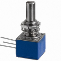
POT 5K OHM CERMET 2W
Manufacturer
Bourns Inc.
Series
81r
Type
Potentiometerr
Specifications of 81A1A-B28-A13L
Adjustment Type
Side Adjustment
Resistance (ohms)
5K
Power (watts)
2W
Tolerance
±10%
Temperature Coefficient
±150ppm/°C
Number Of Turns
Single
Rotation
300°
Resistive Material
Cermet
Termination Style
Through Hole
Actuator Length
22.23mm
Actuator Type
Slotted Shaft
Actuator Diameter
6.35mm
Package / Case
Square - 0.625" L x 0.625" W x 0.625" H (15.88mm x 15.88mm x 15.88mm
Resistance In Ohms
5.00K
Track Resistance
5kohm
Track Taper
Linear
No. Of Turns
1
Resistance Tolerance
± 20%
Power Rating
2W
Potentiometer Mounting
PCB
Resistance
5 KOhms
Taper
Linear
Element Type
Cermet
Shaft Type
Slotted
Shaft Length
7/8 in
Shaft Diameter
1/4 in
Product
Precision Potentiometers & Dials
Angle, Mechanical
300 °
Diameter, Shaft
0.25 "
Dielectric Strength
1500 VAC
Dimensions
0.625"L×0.625"W×0.625"H
Linearity
±5 %
Material, Element
Cermet
Mounting Type
Panel
Power, Rating
2 W
Resistance, Insulation
1000 Megohms
Resolution
Infinite
Rotational Life
100000 Cycles
Temperature, Operating, Maximum
+125 °C
Temperature, Operating, Minimum
-40 °C
Termination
PC Pins
Torque
0.14 to 1.06 N-cm
Lead Free Status / RoHS Status
Lead free / RoHS Compliant
Lead Free Status / RoHS Status
Lead free / RoHS Compliant, Lead free / RoHS Compliant
Available stocks
Company
Part Number
Manufacturer
Quantity
Price
Company:

Part Number:
81A1A-B28-A13L
Manufacturer:
BOURNS
Quantity:
1 000


Specifications are subject to change without notice.
Customers should verify actual device performance in their specific applications.
Product Dimensions
Model 81/82
Single Unit - PC Pins & J-Hook
(.375 ±.015)
"E" Bushing
1/4 " (6.35 mm) Dia. Locking - Single Shaft
Dual Unit - PC Pins & J-Hook
"A" Bushing
3/8 " (9.53 mm) Dia. Plain - Single Shaft
9.50 ± .38
(.312)
(.500 ± .005)
7.92
1/4-32 UNEF
12.7 ± .13
(.216)
"A" BUSHING END FOR SHAFTS UNDER
5.49 OPTIONAL FLAT 16.00 LONG OR 1.52 FROM
81/82 - 5/8 ” Square Single-Turn Panel Control
Terminal outlines shown as solid lines represent PC Pins, available
on Model 81. Dashed line terminal outline represents "J" Hook,
available on Model 82.
MIN.
(.375 ± .005)
(.625 ± .016)
PILOT DIA.
9.53 ± .13
15.88 ± .41
(1.025 ± .031)
(.250 ± .002)
26.04 ± .79
(.425)
10.80
PILOT DIA.
MIN.
6.35 ± .05
(.200 ± .015)
5.08 ± .38
3/8-32 UNEF
(.235 ± .015)
(.63)
5.97 ± .38
(.625 ± .015)
15.88 ± .38
(.400 ± .015)
10.16 ± .38
45 ° ±5 ° X
CHAMFER
12.7,15.88,19.05,22.23± .79
45 ° ±5 ° X (.010)
(5/8 ± 1/32)
CHAMFER
15.88 ± .79
STANDARD
SHAFT SLOT
(.063+.015/-.000)
SHAFT SLOT
(.125 ± .001)
(.031 ± .001)
(.50)
12.7
(1/2, 5/8, 7/8, ± 1/32)
1.60+.38/-.00
.78 ± .03
3.18 ± .03
( 11/16 )
17.46
(1/4 ± 1/32)
(.06)
6.35 ± .03
STANDARD
(.010)
.25
(.031)
(.047)
.25
1.19
.78
DIA.
DEEP
(.200 ± .015)
DIA.
WIDE X
WIDE X
5.08 ± .38
DEEP
(.032)
(.377 ± .015)
.81
9.58 ± .38
(.150)
3.81
(.470)
11.94
DIA.
(3/4 ± 1/32)
STANDARD
Triple Unit - PC Pins & J-Hook
19.05 ± .79
3/8-32 UNEF
(.125)
MAX. 3 PLCS.
"B" Bushing
3/8 " (9.53 mm) Dia. Plain - Single Shaft
OUTER SHAFT 7.47 DIA. OPERATES SECTION #1 INNER SHAFT
3.18
(.210 ± .03)
(.500 ± .005)
"A" Bushing
3/8 " (9.53 mm) Dia. Plain - Concentric Shaft
3/8-32 UNEF
12.70 ± .13
5.33 ± .76
(.625 ± .015)
15.88 ± .38
DIA. OPERATES SECTION #2, #3, & #4 ("G" STYLE)
(.249)
(1.425 ± .047)
(.375 ± .005)
36.20 ± 1.19
(.200 ± .005)
PILOT DIA.
9.53 ± .13
11.13
(.438)
5.08 ± .13
MIN.
(1-1/8 ± 1/32)
Model 81
Suggested PC Board Layout - PC Pins
(Single-Shaft Style Bottom View)
28.58 ± .79
STANDARD
(9.53)
Note: For units with dual concentric shaft styles, a
.100 (2.54) spacer is added between the module(s) driven
by the outer shaft and those driven by the inner shaft.
For G, K, or V shafts, add the spacer between
modules 1 and 2. For L or M shafts, add the spacer
between modules 2 and 3. For N or P shafts, add the
spacer between modules 3 and 4.
.375
TRIPLE CONCENTRIC
(SPECIAL ORDER)
DIMENSIONS ARE:
(.400 ± .015)
(5/8 ± 1/32)
15.88 ± .79
STANDARD
10.16 ± .38
45 ° ±5 ° X
CHAMFER
(.400 ± .005)
(.249 ± .001)
10.16 ± .13
(.063 +.015/-.000)
SHAFT SLOT
1.60 + .38/- .00
6.32 ± .03
(.045)
1.14
(.249 ±.001)
6.32 ± .03
(.1245 ± .001)
DIA.
3.162 ± .025
TYP.
(.010)
(.078 ± .001)
.25
1.98 ± .03
(.047)
DIA.
1.19
WIDE X
DEEP
DIA.
DIA.
DIA.
(INCHES)
Quad Unit - PC Pins & J-Hook
(.200 ± .005)
1
MM
5.08 ± .13
"C" Bushing
1/4 " (6.35 mm) Dia. Plain - Single Shaft
(.250 ± .005)
"C" Bushing
1/4 " (6.35 mm) Dia. Plain - Concentric Shaft
6.35 ± .13
3
2
(1.95)
(.175)
OUTER SHAFT 3.18 DIA. OPERATES SECTION #1 INNER SHAFT
MIN.
.078
4.45
(5/8 ± 1/32)
15.88 ± .79
STANDARD
1/4-32 UNEF
DIA. OPERATES SECTION #2, #3, & #4 ("G" STYLE)
(.250 ± .002)
(.094 ± . 005)
PILOT DIA.
"C" BUSHING END FOR SHAFTS UNDER
(.400 ± .015)
6.35 ± .05
10.16 ± .38
2.39 ± .13 OPTIONAL FLAT 6.35 LONG OR 1.52 FROM
(.125)
(1.825 ± .047)
46.36 ± 1.19
1/4-32 UNEF
Shaft Flat Orientation*
*EXCLUDES MODELS 83 AND 84
(.25)
TYP.
6.35
STANDARD
25.40 ± .79
(1 ± 1/32)
SLOTTED SHAFT
FLATTED SHAFT
1 2 3
(.1245 ± .001)
3.162 ± .025
9.53,12.7,15.88,19.05,22.23 ± .79
(.250)
(3/8, 1/2, 5/8, 3/4, 7/8, ± 1/32)
45 ° ±5 ° X
CHAMFER
(.1245 ± .001)
30 ° ±5 °
3.162 ± .025
120 ° ± 5 ° CCW END
SHAFT SLOT
(.031 ± .010)
.79 ± .25
(.078 ± .001)
14.30
(9/16)
STANDARD
1.98 ± .03
DIA.
(.010)
.25
DIA.
(.06)
(.031)
.79
DEEP
DIA.
WIDE X
Related parts for 81A1A-B28-A13L
Image
Part Number
Description
Manufacturer
Datasheet
Request
R

Part Number:
Description:
POT 10K OHM CERMET 2W
Manufacturer:
Bourns Inc.
Datasheet:
Part Number:
Description:
POT 1K OHM CERMET 2W
Manufacturer:
Bourns Inc.
Datasheet:
Part Number:
Description:
POT 1K OHM CERMET 2W
Manufacturer:
Bourns Inc.
Datasheet:
Part Number:
Description:
POT 5K OHM CERMET 2W
Manufacturer:
Bourns Inc.
Datasheet:
Part Number:
Description:
POT 10K OHM CERMET 2W
Manufacturer:
Bourns Inc.
Datasheet:

Part Number:
Description:
POT 1M OHM 5/8" SQ 1/2W PLAS
Manufacturer:
Bourns Inc.
Datasheet:
Part Number:
Description:
POTENTIOMETER CERMET, 500OHM 10% 2W
Manufacturer:
Bourns Inc.
Datasheet:

Part Number:
Description:
RES,Non-Specified,100KOhms,10+/-% Tol,-1000,1000ppm-TC,6363-Case
Manufacturer:
Bourns Inc.
Datasheet:
Part Number:
Description:
RES,Non-Specified,5KOhms,20+/-% Tol,-1000,1000ppm-TC,6363-Case
Manufacturer:
Bourns Inc.
Datasheet:

Part Number:
Description:
Manufacturer:
Bourns, Inc.
Datasheet:
Part Number:
Description:
11mm Potentiometer
Manufacturer:
Bourns, Inc.
Datasheet: