81C1A-E28-A20L Bourns Inc., 81C1A-E28-A20L Datasheet - Page 4
81C1A-E28-A20L
Manufacturer Part Number
81C1A-E28-A20L
Description
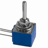
POT 100K OHM CERMET 2W
Manufacturer
Bourns Inc.
Series
81r
Type
Potentiometerr
Datasheet
1.81A1A-B28-A15L.pdf
(6 pages)
Specifications of 81C1A-E28-A20L
Number Of Turns
Single
Termination Style
Through Hole
Temperature Coefficient
±150ppm/°C
Resistance (ohms)
100K
Power (watts)
2W
Tolerance
±10%
Rotation
300°
Adjustment Type
Side Adjustment
Resistive Material
Cermet
Actuator Length
22.23mm
Actuator Type
Slotted Shaft
Actuator Diameter
3.18mm
Package / Case
Square - 0.625" L x 0.625" W x 0.625" H (15.88mm x 15.88mm x 15.88mm
Resistance In Ohms
100K
Resistance
100kohm
Power Rating
2W
Tolerance (+ Or -)
10%
Technology
Cermet
Mounting Style
Panel
Operating Temp Range
-40C to 125C
Failure Rate
Not Required
Shaft Diameter (mm)
3.18mm
Product Diameter (mm)
Not Requiredmm
Product Length (mm)
38.11mm
Product Height (mm)
17.52mm
Product Depth (mm)
15.88mm
Taper
Linear
Element Type
Cermet
Shaft Type
Slotted
Shaft Length
7/8 in
Shaft Diameter
1/8 in
Product
Precision Potentiometers
Track Resistance
100kohm
Track Taper
Linear
No. Of Turns
1
Resistance Tolerance
± 10%
Potentiometer Mounting
Panel
No. Of Gangs
1
Rohs Compliant
Yes
Lead Free Status / RoHS Status
Lead free / RoHS Compliant
Lead Free Status / RoHS Status
Compliant, Lead free / RoHS Compliant
Available stocks
Company
Part Number
Manufacturer
Quantity
Price
Company:

Part Number:
81C1A-E28-A20L
Manufacturer:
BOURNS
Quantity:
1 000


Product Dimensions
Model 81/82
Single Unit - PC Pins & J-Hook
Dual Unit - PC Pins & J-Hook
Terminal outlines shown as solid lines represent PC Pins, available
on Model 81. Dashed line terminal outline represents "J" Hook,
available on Model 82.
81/82 - 5/8 ” Square Single-Turn Panel Control
(.625 ± .016)
15.88 ± .41
(1.025 ± .031)
(.200 ± .015)
5.08 ± .38
26.04 ± .79
(.235 ± .015)
5.97 ± .38
(.625 ± .015)
15.88 ± .38
(.400 ± .015)
10.16 ± .38
(.50)
12.7
(.200 ± .015)
5.08 ± .38
(.032)
(.377 ± .015)
.81
9.58 ± .38
(.150)
3.81
(.470)
11.94
DIA.
MAX. 3 PLCS.
(.210 ± .03)
5.33 ± .76
Triple Unit - PC Pins & J-Hook
(.625 ± .015)
15.88 ± .38
(1.425 ± .047)
36.20 ± 1.19
(.200 ± .005)
5.08 ± .13
Model 81
Suggested PC Board Layout - PC Pins
(Single-Shaft Style Bottom View)
Note: For units with dual concentric shaft styles, a
2.54 (.100) spacer is added between the module(s) driven
by the outer shaft and those driven by the inner shaft.
For G, K, or V shafts, add the spacer between
modules 1 and 2. For L or M shafts, add the spacer
between modules 2 and 3. For N or P shafts, add the
spacer between modules 3 and 4.
DIMENSIONS:
(.400 ± .015)
10.16 ± .38
(.400 ± .005)
10.16 ± .13
(.045)
1.14
DIA.
TYP.
(INCHES)
Customers should verify actual device performance in their specifi c applications
MM
Quad Unit - PC Pins & J-Hook
1
(.200 ± .005)
5.08 ± .13
3
2
(.400 ± .015)
10.16 ± .38
(1.825 ± .047)
46.36 ± 1.19
Specifi cations are subject to change without notice.
Shaft Flat Orientation*
*EXCLUDES MODELS 83 AND 84
TYP.
SLOTTED SHAFT
FLATTED SHAFT
1 2 3
30 ° ±5 °
120 ° ± 5 ° CCW END
Related parts for 81C1A-E28-A20L
Image
Part Number
Description
Manufacturer
Datasheet
Request
R

Part Number:
Description:
POT 10K OHM CERMET 2W
Manufacturer:
Bourns Inc.
Datasheet:
Part Number:
Description:
POT 5K OHM CERMET 2W
Manufacturer:
Bourns Inc.
Datasheet:
Part Number:
Description:
POT 10K OHM CERMET 2W
Manufacturer:
Bourns Inc.
Datasheet:
Part Number:
Description:
POT 100K OHM CERMET 2W
Manufacturer:
Bourns Inc.
Datasheet:
Part Number:
Description:
POT 5K OHM CERMET 2W
Manufacturer:
Bourns Inc.
Datasheet:

Part Number:
Description:
POTENTIOMETER CERMET, 50KOHM 10% 2W
Manufacturer:
Bourns Inc.
Datasheet:
Part Number:
Description:
POTENTIOMETER CERMET, 50KOHM 10% 2W
Manufacturer:
Bourns Inc.
Datasheet:

Part Number:
Description:
Panel Mount Potentiometers 5/8 5K 20% Square Single Turn
Manufacturer:
Bourns Inc.
Datasheet:
Part Number:
Description:
Panel Mount Potentiometers 5/8 50K 20% Square Single Turn
Manufacturer:
Bourns Inc.
Datasheet:
Part Number:
Description:
Panel Mount Potentiometers 5/8 10K 20% Square Single Turn
Manufacturer:
Bourns Inc.
Datasheet:

Part Number:
Description:
Manufacturer:
Bourns, Inc.
Datasheet:
Part Number:
Description:
11mm Potentiometer
Manufacturer:
Bourns, Inc.
Datasheet: