95A1A-B24-B15 Bourns Inc., 95A1A-B24-B15 Datasheet - Page 3
95A1A-B24-B15
Manufacturer Part Number
95A1A-B24-B15
Description
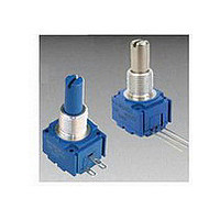
POT 10K OHM 5/8"
Manufacturer
Bourns Inc.
Series
95r
Type
Potentiometerr
Specifications of 95A1A-B24-B15
Number Of Turns
Single
Termination Style
Solder Lug
Temperature Coefficient
±1000ppm/°C
Resistance (ohms)
10K
Power (watts)
0.5W, 1/2W
Tolerance
±20%
Rotation
300°
Adjustment Type
Side Adjustment
Resistive Material
Conductive Plastic
Actuator Length
19.05mm
Actuator Type
Slotted Shaft
Actuator Diameter
6.35mm
Package / Case
Square - 0.625" L x 0.625" W x 0.500" H (15.88mm x 15.88mm x 12.70mm)
Resistance In Ohms
10.0K
Resistance
10kohm
Power Rating
1/2W
Tolerance (+ Or -)
20%
Technology
Cermet
Mounting Style
Panel
Operating Temp Range
-40C to 125C
Failure Rate
Not Required
Shaft Diameter (mm)
6.35mm
Product Diameter (mm)
Not Requiredmm
Product Length (mm)
31.75mm
Product Height (mm)
17.47mm
Product Depth (mm)
15.88mm
Taper
Linear
Element Type
Conductive Plastic
Shaft Type
Slotted
Shaft Length
3/4 in
Shaft Diameter
1/4 in
Operating Temperature Range
- 40 C to + 125 C
Product
Panel Mount Potentiometers
Lead Free Status / Rohs Status
Lead free / RoHS Compliant
Other names
95A1AB24B15
Q1082980
Q1082980


Specifi cations are subject to change without notice.
Customers should verify actual device performance in their specifi c applications.
(.032)
(.400 ± .012)
(.400 ± .012)
10.16 ± 0.30
10.16 ± 0.30
Product Dimensions
0.81
DIA.
(.175 ± .015)
4.45 ± .38
Model 93 PC Pin Terminals, "L" Pattern
Model 95 Solder Lug Terminals, "Triangular" Pattern
Model 91 PC Pin Terminals, In-Line
TYP.
Model 91, 92, 93, 94 & 95 - 5/8 ” Square Single-Turn Panel Control
10.16
(.40)
1
2
3
1
3
R2
R2
(.900 ± .017)
(.900 ± .017)
22.86 ± 0.43
22.86 ± 0.43
2
1
2
3
1
3
R1
R1
2
(.175 ± .015)
4.45 ± .38
(.200 ± .015)
(.435 ± .008)
(.500 ± .009)
(.435 ± .008)
11.05 ± 0.20
12.70 ± .229
11.05 ± 0.20
(.220 ± .008)
(.500 ± .009)
5.08 ± 0.38
12.70 ± .229
MOUNTING
5.59 ± .20
(.031 ± .010)
MOUNTING
SURFACE
(.031 ± .010)
0.79 ± .025
SURFACE
0.79 ± .025
L
L
SEE
HOW TO ORDER
CHART FOR
BUSHING OPTIONS.
SEE
HOW TO ORDER
CHART FOR
BUSHING OPTIONS.
SEE
NEXT PAGE
FOR SHAFT
OPTIONS.
SEE
NEXT PAGE
FOR SHAFT
OPTIONS.
(.100)
TOLERANCES EXCEPT AS SHOWN: DECIMAL .XXX ± (.015 ) FRACTION ± 1/64
2.54
(.093 ± .003)
(.093 ± .003)
2.36 ± 0.08
2.36 ± 0.08
(.540 ± .015)
(.054 ± .003)
(.540 ± .015)
(.054 ± .003)
13.72 ± 0.38
13.72 ± 0.38
1.37 ± 0.08
1.37 ± 0.08
(.100)
2.54
DIA.
DIA.
(.200 ± .040)
5.08 ± 1.02
“A” STYLE
“A” STYLE
R
R
A.R. LUG
A.R. LUG
(.047)
(.047)
1.19
1.19
3 PLCS.
(.100)
(.100)
(.080)
2.54
2.54
2.03
(.100)
(.100)
2.54
2.54
(.040) WIDE X (.090) LONG
1.02
15.88
(.625)
15.88
(.625)
3 PLCS.
(.602 ± .022)
(.500 ± .040)
15.29 ± 0.56
12.70 ± 1.02
.XX ±
.381
(.030 ± .002)
(.030 ± .002)
2.29
0.76 ± 0.05
0.76 ± 0.05
(.38)
9.65
TYP.
TYP.
(.016)
.41
(.312)
(.375)
(.312)
(.375)
ANGLE ±5 °
7.92
9.53
7.92
9.53
Model 92 J-Hooked
Terminals, In-Line
Model 94 J-Hooked
Terminals, "L" Pattern
Shaft Flat Orientation
R. MAX.
(.032)
.81
3 2 1
3 2 1
(.20)
5.08
MAX. TYP.
(.150)
3.81
120 ° ± 5 ° STD.
FLAT ORIENTATION
(SHAFT AT CCW END)
(.21 ± .03)
5.33 ± .76
CCW
1
(.031) 2 PLCS.
(.06)
.79
1.52
POTENTIOMETER
(.010)
.254
GAP
2
(.06)
1.52
GAP
3
Related parts for 95A1A-B24-B15
Image
Part Number
Description
Manufacturer
Datasheet
Request
R

Part Number:
Description:
POT SNGL TURN 7/8"10K OHM
Manufacturer:
Bourns Inc.
Datasheet:

Part Number:
Description:
Panel Mount Potentiometers 5/8 5K 10% Square Single Turn
Manufacturer:
Bourns Inc.
Datasheet:
Part Number:
Description:
POT 5K OHM 5/8" SQ 2W CERMET
Manufacturer:
Bourns Inc.
Datasheet:
Part Number:
Description:
Panel Mount Potentiometers 5/8 100K 10% Square Single Turn
Manufacturer:
Bourns Inc.
Datasheet:
Part Number:
Description:
RES,Non-Specified,10KOhms,10+/-% Tol,-150,150ppm-TC,5063-Case
Manufacturer:
Bourns Inc.
Datasheet:
Part Number:
Description:
RES,Non-Specified,100KOhms,10+/-% Tol,-150,150ppm-TC,5063-Case
Manufacturer:
Bourns Inc.
Datasheet:
Part Number:
Description:
RES,Non-Specified,500KOhms,20+/-% Tol,-1000,1000ppm-TC,5063-Case
Manufacturer:
Bourns Inc.
Datasheet:

Part Number:
Description:
PANEL CONTROL - 5/8" (16MM) ST-CP
Manufacturer:
Bourns Inc.
Datasheet:
Part Number:
Description:
RES,Non-Specified,10KOhms,10+/-% Tol,-150,150ppm-TC,5063-Case
Manufacturer:
Bourns Inc.
Datasheet:
Part Number:
Description:
PANEL CONTROL - 5/8" (16MM) ST-CP
Manufacturer:
Bourns Inc.
Datasheet:

Part Number:
Description:
Manufacturer:
Bourns, Inc.
Datasheet:
Part Number:
Description:
11mm Potentiometer
Manufacturer:
Bourns, Inc.
Datasheet: