EVN-DJAA03B53 Panasonic - ECG, EVN-DJAA03B53 Datasheet - Page 3
EVN-DJAA03B53
Manufacturer Part Number
EVN-DJAA03B53
Description
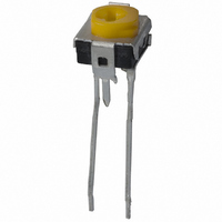
POT 5K OHM 6MM CARBON TOP ADJ
Manufacturer
Panasonic - ECG
Series
EVN-DJAr
Datasheet
1.EVN-DCAA03B53.pdf
(3 pages)
Specifications of EVN-DJAA03B53
Resistance (ohms)
5K
Power (watts)
0.1W, 1/10W
Taper
Linear
Tolerance
±30%
Number Of Turns
Single
Adjustment Type
Top Adjustment
Mounting Type
Through Hole
Resistive Material
Carbon
Package / Case
Square - 0.264" L x 0.252" W x 0.250" H (6.70mm x 6.40mm x 6.35mm)
Resistance In Ohms
5.00K
Lead Free Status / RoHS Status
Lead free / RoHS Compliant
Temperature Coefficient
-
Other names
DJA53TB
EVNDJAA03B53
EVNDJAA03B53


■
● Top-adjust ............................................................................................................................................................... EVNDJA
● Top-adjust ............................................................................................................................................................... EVNDXA
● Side-adjust ............................................................................................................................................................ EVNDCA
Design and specifi cations are each subject to change without notice. Ask factory for the current technical specifi cations before purchase and/or use.
Should a safety concern arise regarding this product, please be sure to contact us immediately.
Radial Taping Prod ucts
No. 3
No. 4
No. 5
Knob color
Knob color
Knob color
Circuit diagram
PWB mounting hole
for reference
View from mounting side
2-0.5
#1
PWB mounting hole for reference
View from mounting side
0.8+0.1
5.00±0.05
2-0.85
+
CW
0.1
0
#1
#2
φ1.3
Orange yellow
Orange yellow
Orange yellow
6.4
0.6
#2
#1
#3
φ2-1.0
#3
+
6.4
#2
0.1
0
#3
0.8±0.1
2-0.85
2-0.5
+
φ3.2
0.1
0
φ2–1.0
φ2
φ3.2
Resistance
Resistance
+
1 max.
0.1
0
(2.05)
Mounting surface
+
Carbon Composition Trimmer Po ten ti om e ters/EVND
(φ2.5)
0.1
0
0.3
0.9
1.7
Circuit diagram
5.00±0.05
#1
(0.25)
3 max.
3.4
– EV24 –
5.00±0.05
3
6
6.8
CW
6
Circuit diagram
3.4
#1
2.50±0.35
0.3
#2
φ1.3
Mounting
surface
(φ2.5)
φ1.3
1 max.
(0.5)
#3
2-φ1.0
PWB mounting
hole for reference
+
CW
The pattern foil of PWB shall
not be in this dotted square
area.
0.1
0
0.6
The pattern foil of PWB shall
not be in this dotted square
area.
#2
+
0.1
0
Mounting
surface
+
#3
0.1
0
0.3±0.1
0.3±0.1
3.0
1 max.
1 max.
3.0±0.3
0.3±0.1
+
–
0.5
0.2
(0.25)
0.3
Resistance
1 max.
0.25
1 max.
(1.7)
3.85±0.70
6.35±1.30
1.3 max.
5.0
4.4 min.
2.2
5.0±0.8 3.85±0.70
12.7±0.3
+
0.8
0
6.35±1.30 P=12.7±0.3
6.35±1.30
5.0±0.8
6.4
12.7±1.0
12.7±1.0
3.85±0.70
1.3 max.
0.8±0.1
1.3 max.
1.3 max.
12.7±1.0
0.5
A
A
φ4.0±0.3
P=12.7±0.3
+
0.1
0
A
Adhesive tape
φ40±0.3
1.3 max.
1.3 max.
A
Mounting
surface
Adhesive tape shall
not be over from
base paper.
A
Adhesive tape
A
A
A
EIAJ RC-1008 shall be applied
to items not specified here.
Adhesive tape shall
not be over from
base paper.
Adhesive tape shall
not be over from
base paper.
–
–
φ4.0±0.3
A
A
00
A
Section
Section
–
2 max.
A
Sep. 2010
2 max.
2 max.
Section
Related parts for EVN-DJAA03B53
Image
Part Number
Description
Manufacturer
Datasheet
Request
R

Part Number:
Description:
POT 10K OHM 6MM CARBON TOP ADJ
Manufacturer:
Panasonic - ECG
Datasheet:
Part Number:
Description:
POT 2K OHM 6MM CARBON TOP ADJ
Manufacturer:
Panasonic - ECG
Datasheet:
Part Number:
Description:
POT 20K OHM 6MM CARBON TOP ADJ
Manufacturer:
Panasonic - ECG
Datasheet:
Part Number:
Description:
POT 100K OHM 6MM CARBON TOP ADJ
Manufacturer:
Panasonic - ECG
Datasheet:
Part Number:
Description:
POT 200 OHM 6MM CARBON TOP ADJ
Manufacturer:
Panasonic - ECG
Datasheet:
Part Number:
Description:
POT 500 OHM 6MM CARBON TOP ADJ
Manufacturer:
Panasonic - ECG
Datasheet:
Part Number:
Description:
POT 1K OHM 6MM CARBON TOP ADJ
Manufacturer:
Panasonic - ECG
Datasheet:
Part Number:
Description:
POT 200K OHM 6MM CARBON TOP ADJ
Manufacturer:
Panasonic - ECG
Datasheet:
Part Number:
Description:
POT 500K OHM 6MM CARBON TOP ADJ
Manufacturer:
Panasonic - ECG
Datasheet:
Part Number:
Description:
POT 50K OHM 6MM CARBON TOP ADJ
Manufacturer:
Panasonic - ECG
Datasheet:


Part Number:
Description:
MICROPHONE OMNI 6X2.2MM W/CAP
Manufacturer:
Panasonic - ECG
Datasheet:

Part Number:
Description:
CAP .01UF 100V PEN FILM 1210 5%
Manufacturer:
Panasonic - ECG
Datasheet:

Part Number:
Description:
FILTER LINE 23.3MH 2A
Manufacturer:
Panasonic - ECG
Datasheet:

Part Number:
Description:
SAW FILTER PCS 1960 MHZ 50/150
Manufacturer:
Panasonic - ECG
Datasheet: