3314G-1-103E Bourns Inc., 3314G-1-103E Datasheet - Page 2
3314G-1-103E
Manufacturer Part Number
3314G-1-103E
Description
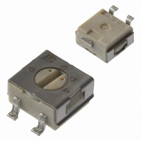
POT 10K OHM 4MM SQ CERMET SMD
Manufacturer
Bourns Inc.
Series
3314 - Sealedr
Specifications of 3314G-1-103E
Tolerance
±20%
Number Of Turns
Single
Temperature Coefficient
±100ppm/°C
Resistance (ohms)
10K
Power (watts)
0.25W, 1/4W
Adjustment Type
Top Adjustment
Mounting Type
Surface Mount
Resistive Material
Cermet
Package / Case
Square - 0.177" L x 0.177" W x 0.100" H (4.50mm x 4.50mm x 2.54mm)
Resistance In Ohms
10.0K
Resistance
10 KOhms
Power Rating
0.25 Watt (1/4 Watt)
Operating Temperature Range
- 55 C to + 125 C
Element Type
Cermet
Dimensions
4.5 mm W x 4.50 mm L x 2.55 mm H
Product
Trimmers
Termination Style
SMD/SMT
Taper
Linear
Angle, Mechanical
240 °
Dielectric Strength
500 VAC
Insulation Resistance
100 Megohms (Min.) @ 500 VDC
Load Life
1000 hr, 0.25 W @ 70°C
Material, Element
Cermet
Power, Rating
0.25 W
Resistance, Insulation
100 Megohms
Resolution
Infinite
Rotational Life
100 Cycles
Standards
Meets EIA⁄EIAJ⁄IPC⁄VECI SMD Standard Trimmer Designs
Temperature, Operating, Maximum
+125 °C
Temperature, Operating, Minimum
-55 °C
Termination
SMT
Torque
180 g-cm
Lead Free Status / RoHS Status
Lead free / RoHS Compliant
Lead Free Status / RoHS Status
Lead free / RoHS Compliant, Lead free / RoHS Compliant
Other names
3314G-103ETR
Available stocks
Company
Part Number
Manufacturer
Quantity
Price
Company:

Part Number:
3314G-1-103E
Manufacturer:
BOURNS
Quantity:
20 000
Company:
Part Number:
3314G-1-103E
Manufacturer:
BOURNS
Quantity:
6 000
Company:
Part Number:
3314G-1-103E
Manufacturer:
BOURNS
Quantity:
211
Part Number:
3314G-1-103E
Manufacturer:
BOURNS/伯恩斯
Quantity:
20 000


3314R-1
(.244)
3314H-1
6.20
(.092)
Product Dimensions
2.35
3
3
(.197)
(.197)
5.00
3314 - 4 mm Square Trimpot
(.177)
5.00
4.50
2
2
(.197)
5.00
1
1
(.100)
2.55
(.244)
(.024 ± .004)
(.177)
(.177)
6.20
4.50
4.50
0.6 ± 0.1
3 PLCS.
(.031 ± .004)
(.051 ± .004)
(.248)
0.80 ± 0.10
1.30 ± 0.10
6.30
2 PLCS.
(.126)
THRU.
(.197)
DIA.
3.2
5.00
(.100)
2.55
(.020 ± .005)
0.51 ± 0.13
TYP.
PINS ARE PARALLEL
OUTSIDE WHEN
(.197 ± .004)
5.00 ± 0.10
TYP.
(.020 ± .005)
0.51 ± 0.13
(.008)
RECOMMENDED PCB
LAYOUT
2 PLCS.
0.20
(.051)
TYP.
1.3
(.100)
2.55
(.157)
(.100)
DIA. TYP.
4.00
2.55
(.031)
(.079)
(.090)
0.80
(.216)
2.0
2.3
(.008)
R 0.13
5.5
0.20
TYP.
2 PLCS.
(.051)
TYP.
(.005)
MAX.
TYP.
1.3
TAPE
REEL
* Embossed Tape Designator "E"
** Embossed Tape Designator "G"
Meets EIA specification 481.
(J, G Styles)
(.060 + .004/ - .000)
(.512 ± .020)
13.0 ± .51
1.5 + .10/ –.00
(See How To Order chart for further information.)
Packaging Specifi cations - J, G and R Styles
®
(.108 ± .004)
(.157 ± .004)
(.070) ± .010)
(.079 ± .020)
2.74 ± .10
4.00 ± .10
DIA.
(.069 ± .004)
2.00 ± .05
1.78 ± .25
CCW
1.75 ± .10
(.472 ± .012)
Trimming Potentiometer
12.00 ± .30
(13.00 ± .079)
1
(7.00 ± .080)
177.8 ± 2.03
330.2 ± 2.0
DIA.
CLOCKWISE
EQUAL SPACED 3 PLCS.
DIA.**
DIA.*
2
(.827 ± .031)
21.01 ± .79
WIPER
(.217 ± .020)
(.488 + .079/ - .000)
12.4 + 2.01/ -.000
5.52 ± 0.5
Customers should verify actual device performance in their specifi c applications.
DIA.
(.207 ± .004)
(.254 ± .004)
(.014)
5.26 ± .10
6.45 ± .10
3
.36
(.207 ± .004)
(.315 ± .008)
(.105 ± .010)
(2.330 ± .080)
5.26 ± .10
8.00 ± .20
59.18 ± 2.03
2.67 ± .25
CW
MAX.
(G)
(J)
(.512 ± .020)
TAPE
REEL
(R Style)
13.0 ± .508
* Embossed Tape Designator "E"
** Embossed Tape Designator "G"
Meets EIA specification 481.
TOLERANCES: ±
(.059 + .004-.00)
1.5 + .10/ –.00
EQUAL SPACED
DIA.
(See How To Order chart for further information.)
(.130 ± .004)
(.070 ± .010)
(.079 ± .002)
1.78 ± .254
Specifi cations are subject to change without notice.
3.29 ± .10
(.157 ± .004)
2.00 ± .05
3 PLCS.
4.00 ± .10
DIA.
(.068 ± .004)
1.75 ± .10
(13.00 ± .079)
(7.00 ± .080)
177.8 ± 2.03
DIMENSIONS:
330.2 ± 2.0
(.010)
0.25
DIA.**
DIA.*
(.000 ± .000)
21.01 ± .789
(INCHES)
EXCEPT WHERE NOTED
MM
DIA.
6° ± 2°
(.488 + .079/-.000)
(.217 ± .002)
12.4 + 2.01/ -.000
(4.72
5.52 ± 0.05
(.059 ± .012)
1.50 + 0.30
12.00 ± .30
(.254 ± .004)
6.45 ± 0.10
(.207 ± .004)
5.26 ± .10
(0.12)
(.105 ± .010)
(2.330 ± .080)
.30 MAX.
2.67 ± .254
59.18 ± 2.03
± .012
DIA.
Related parts for 3314G-1-103E
Image
Part Number
Description
Manufacturer
Datasheet
Request
R

Part Number:
Description:
POT, TRIM, 20OHM, 1 TURN, 20%, SMD
Manufacturer:
Bourns Inc.
Datasheet:

Part Number:
Description:
POT 1K OHM 4MM SQ CERMET SMD
Manufacturer:
Bourns Inc.
Datasheet:
Part Number:
Description:
POT 5K OHM 4MM SQ CERMET SMD
Manufacturer:
Bourns Inc.
Datasheet:
Part Number:
Description:
POT 50K OHM 4MM SQ CERMET SMD
Manufacturer:
Bourns Inc.
Datasheet:
Part Number:
Description:
POT 500 OHM 4MM SQ CERMET SMD
Manufacturer:
Bourns Inc.
Datasheet:
Part Number:
Description:
POT 2K OHM 4MM SQ CERMET SMD
Manufacturer:
Bourns Inc.
Datasheet:
Part Number:
Description:
POT 20K OHM 4MM SQ CERMET SMD
Manufacturer:
Bourns Inc.
Datasheet:
Part Number:
Description:
POT 200 OHM 4MM SQ CERMET SMD
Manufacturer:
Bourns Inc.
Datasheet:
Part Number:
Description:
POT 100K OHM 4MM SQ CERMET SMD
Manufacturer:
Bourns Inc.
Datasheet:
Part Number:
Description:
POT 25K OHM 4MM SQ CERMET SMD
Manufacturer:
Bourns Inc.
Datasheet:

Part Number:
Description:
TRIMPOT 50 OHM 4MM CERMET SMD
Manufacturer:
Bourns Inc.
Datasheet:
Part Number:
Description:
TRIMPOT 10 OHM 4MM CERMET SMD
Manufacturer:
Bourns Inc.
Datasheet:
Part Number:
Description:
POT, TRIMMER, 1MOHM, 1 TURN, SMD
Manufacturer:
Bourns Inc.
Datasheet:
Part Number:
Description:
POT 200K OHM 4MM SQ CERMET SMD
Manufacturer:
Bourns Inc.
Datasheet:
Part Number:
Description:
POT 100 OHM 4MM SQ CERMET SMD
Manufacturer:
Bourns Inc.
Datasheet: