HLS30ZE-NT POWER ONE, HLS30ZE-NT Datasheet - Page 7
HLS30ZE-NT
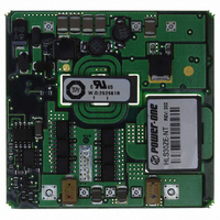
Manufacturer Part Number
HLS30ZE-NT
Description
CONV DC-DC 48V IN 3.3V OUT 100W
Manufacturer
POWER ONE
Series
HLSr
Type
Isolatedr
Datasheet
1.HLS30ZE-NT.pdf
(10 pages)
Specifications of HLS30ZE-NT
Output
3.3V
Number Of Outputs
1
Power (watts)
100W
Mounting Type
Through Hole
Voltage - Input
36 ~ 75V
Package / Case
9-DIP Module, 1/2 Brick
1st Output
3.3 VDC @ 30A
Size / Dimension
2.40" L x 2.28" W x 0.43" H (61mm x 57.9mm x 10.9mm)
Power (watts) - Rated
100W
Operating Temperature
-40°C ~ 100°C
Efficiency
89%
Approvals
CSA, TUV, UL
Lead Free Status / RoHS Status
Contains lead / RoHS non-compliant
3rd Output
-
2nd Output
-
4th Output
-
Other names
179-2247


The general equation (1) for changing the output
voltage on the standard trim modules is invariant, but
the constants in the equation change due to different
internal design.
Where A and B are constants from the table below,
and ΔV is the absolute value of the desired change
in the output voltage in Volts.
Negative-Trim, HLS40 models (No P/N suffix)
If an external resistor is placed between the Trim pin
and (+) Sense pin, the output voltage decreases.
The equation determines the required external
resistor value to obtain an output voltage change of
Δ%∗.
R
If an external resistor is used between Trim pin and
(–) Sense pin, the output voltage increases. The
equation determines the required external resistor
value to obtain an output voltage change of Δ%∗.
Where R1 and R2 are constants from the table
below
∗ NOTE: Δ% - Percentage output voltage trim down or up.
FEB 17, 2006 revised to JUL 25, 2006
R
trim-dn = R1*(---------------------------) - R2 kΩ
TRIM
HLS30ZG
HLS30ZE
HLS30ZD
HLS40ZA
HLS40ZB
Model
HLS30ZG
R
HLS30ZE
HLS30ZD
HLS40ZA
HLS40ZB
Model
=
trim-up = (------------- - R2) kΩ
A
−
Δ
B
V
×
below
below
Vo*(100-Δ%)-122.5
3.77
2.07
1.27
See
See
Δ
A
122.5*R1
V
Trim Up
Vo*Δ%
Vo*Δ%
,
R1 (kΩ)
kΩ
0. 223
3.077
1.690
1.039
0.475
6.81
3.92
3.92
n/a
n/a
B
below
below
11.58
1.31
See
See
3.5
A
Trim Down
(1)
R2 (kΩ)
6.81
3.92
3.92
0.15
9.88
5.61
4.95
1
n/a
n/a
B
Page 7 of 10
HLS Series DC-DC Converter Data Sheet
48 VDC Input, 30 & 40 Amp Half-Bricks
Optional Positive Trim all models (–T, P/N suffix)
The -T option units trim up with a resistor from the
TRIM pin to the (+) Sense pin and trim down with a
resistor from the TRIM pin to the (–) Sense pin as
shown in the Figure 8.
The equations below determine the trim resistor
value required to achieve a ΔV change in the output
voltage.
where ΔV% is the output voltage change expressed
in percents of the nominal output voltage, Vout.
NOTES:
1.
2.
3.
R
R
UP
DOWN
When the output voltage is trimmed up, the output power
from the converter must not exceed its maximum rating. This
is determined by measuring the output voltage on the output
pins, and multiplying it by the output current.
In order to avoid creating apparent load regulation
degradation, it is important that the trim resistors are
connected directly to the remote sense pins, and not to the
load or to traces going to the load.
The HLS Series converters will trim down further than the
10% limit. In general, this is permissible. The user must
confirm that the results are acceptable in his application.
=
Vout
Figure 8. HLS Series Positive Trim Schematic
=
. 1
Δ
100
×
225
V
(
100
%
×
Δ
−
+
V
2
Δ
%
, kΩ
V
%)
−
100
+
Δ
www.power-one.com\
2
V
×
%
Δ
V
%
,kΩ
Related parts for HLS30ZE-NT
Image
Part Number
Description
Manufacturer
Datasheet
Request
R

Part Number:
Description:
SWITCHING POWER SUPPLIES, SINGLE OUTPUT, 80 WATTS
Manufacturer:
POWER ONE
Datasheet:
Part Number:
Description:
HAS SERIES - 30 WATT
Manufacturer:
POWER ONE
Datasheet:
Part Number:
Description:
SINGLE OUTPUT
Manufacturer:
POWER ONE
Datasheet:

Part Number:
Description:
BRS DC/DC converters(1.5 WATT)
Manufacturer:
Power-One
Datasheet:
Part Number:
Description:
3...15 Watt DC-DC Converter
Manufacturer:
Power-One
Datasheet:
Part Number:
Description:
HBS SERIES - 100 WATT
Manufacturer:
Power-One
Datasheet:
Part Number:
Description:
3...15 Watt DC-DC Converter
Manufacturer:
Power-One
Datasheet:
Part Number:
Description:
BUS DC/DC converters(3 WATT)
Manufacturer:
Power-One
Datasheet:
Part Number:
Description:
HES SERIES 150 WATT
Manufacturer:
Power-One
Datasheet:
Part Number:
Description:
1.25 WATT
Manufacturer:
Power-One
Datasheet: