CC10-4805SR-E TDK Corporation, CC10-4805SR-E Datasheet - Page 17
CC10-4805SR-E
Manufacturer Part Number
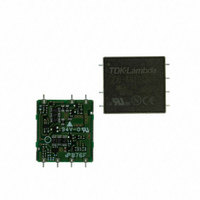
CC10-4805SR-E
Description
CONV DC/DC 10W SNGL 48V 5V SMD
Manufacturer
TDK Corporation
Series
CC-Er
Type
Isolatedr
Datasheets
1.CC1R5-0505SF-E.pdf
(2 pages)
2.CC1R5-0505SF-E.pdf
(21 pages)
3.CC10-2412DR-E.pdf
(18 pages)
Specifications of CC10-4805SR-E
Output
5V
Number Of Outputs
1
Power (watts)
10W
Mounting Type
Surface Mount
Voltage - Input
36 ~ 76V
Package / Case
7-SMD Module
1st Output
5 VDC @ 2A
Size / Dimension
1.40" L x 0.89" W x 0.35" H (35.6mm x 22.6mm x 8.8mm)
Power (watts) - Rated
10W
Operating Temperature
-40°C ~ 85°C
Approvals
CE, CSA, EN, UL
Lead Free Status / RoHS Status
Lead free / RoHS Compliant
3rd Output
-
2nd Output
-
4th Output
-
Other names
445-3310
CC10-4805SR-E
CC104805SRE
CC10-4805SR-E
CC104805SRE


Control Functions/Connections
With the ±12V, 24V single output is possible by opening the COM
terminal and TRM terminal. Also, 30V single output is possible
when opening the COM terminal and connecting the TRM terminal
with the –Vout terminal.
DIP/SMD Models
Part No.
CCx
∗
Fig.5
SIP Model
Part No.
CC3–xx12DS–E
Fig.7
• All specifications are subject to change without notice.
To be replaced by 1R5(1.5W), 3(3W), 6(6W) and 10(10W).
+Vin
–Vin
∗
–xx12Dx–E
Load
+Vout
–Vout
COM
TRM
24V
COM terminal
Open
Open
COM terminal
Open
Open
24V
TRM terminal
Open
Connected with
TRM terminal
Open
Connected with
–Vout
–Vout
Fig.6
Fig.8
+Vin
–Vin
Load
+Vout
–Vout
COM
TRM
30V
Single output
24V
30V
Single output
24V
30V
30V
Fig.
5
6
Fig.
7
8
OUTPUT VARIABILITY FUNCTION
(ADDING EXTERNAL RESISTANCE)
(1.5 to 10W Types)
The output voltage can be adjusted within the range shown in the
following table by connecting resistance (Ra, Rb) between the
TRM terminal and the –Vout terminal, or between the TRM termi-
nal and the +Vout terminal.
Please take note that it is necessary to derate the output current to
match the maximum power when the output voltage is setted
higher.
DIP/SMD Models
Part No.
CCx
CCx–xx05Sx–E
CCx–xx12Sx–E
CCx–xx12Dx–E
∗
Calculate the output voltage Vout(V) from the connected resistance Ra,
Rb(kΩ)
Calculate the connected resistance Ra and Rb(kΩ) from the set output
voltage Vout(V).
Fig.9
Fig.11
To be replaced by 1R5(1.5W), 3(3W), 6(6W) and 10(10W).
Set the output voltage higher by adding resistance Ra between
the TRM terminal/–Vout terminal.
Set the output voltage lower by adding resistance Rb between
the TRM terminal/+Vout terminal.
Set the output voltage higher by adding resistance Ra between
the TRM terminal/–Vout terminal.
Set the output voltage lower by adding resistance Rb between
the TRM terminal/+Vout terminal.
∗
∗1
∗2
∗3
∗4
∗5
∗6
∗7
∗8
∗1
∗2
∗3
∗4
∗5
∗6
∗7
∗8
–xx03Sx–E
Vout=3.3+9.59/(32+Ra)
Vout=5.01+17.64/(17.8+Ra)
Vout=12.01+50.53/(16.9+Ra)
Vout=12.02+53.55/(18+Ra)
Vout=3.3–15.53/(39.6+Rb) [Rb
Vout=5.01–52.55/(31.8+Rb) [Rb
Vout=12.01–431.1/(57+Rb) [Rb
Vout=12.02–968.5/(103+Rb) [Rb
Ra=9.59/(Vout–3.3)–32
Ra=17.64/(Vout–5.01)–17.8
Ra=50.53/(Vout–12.01)–16.9
Ra=53.55/(Vout–12.02)–18
Rb=15.53/(3.3–Vout)–39.6
Rb=52.55/(5.01–Vout)–31.8
Rb=431.1/(12.01–Vout)–57
Rb=968.5/(12.02–Vout)–103
+Vout
+Vout
–Vout
–Vout
COM
TRM
TRM
Ra
Ra
Connecting –Vout
with Ra
3.3 to 3.6V
5 to 6V
12 to 15V
±12 to ±15V
+12 to +15V
–12 to –15V
Load
Load
3.3 to 3.6V
5 to 6V
12 to 15V
∗2
∗3
∗1
∗4
Fig.10
Fig.12
002-05 / 20061129 / ea335_cc_e.fm
62]
620]
Fig.
9
9
9
11
160]
1500]
+Vout
+Vout
–Vout
–Vout
COM
TRM
TRM
Connecting +Vout
with Rb
3.15 to 3.3V
4.75 to 5V
11.4 to 12V
±11.4 to ±12V
Rb
Rb
+11.4 to +12V
–11.4 to –12V
∗6
∗7
Load
Load
∗5
∗8
3.15 to 3.3V
4.75 to 5V
11.4 to 12V
(17/21)
Fig.
10
10
10
12
Related parts for CC10-4805SR-E
Image
Part Number
Description
Manufacturer
Datasheet
Request
R

Part Number:
Description:
CONV DC/DC 10W DUL 48V +-12V PCB
Manufacturer:
TDK Corporation
Datasheet:

Part Number:
Description:
CONV DC/DC 10W DUL 24V +-12V SMD
Manufacturer:
TDK Corporation
Datasheet:
Part Number:
Description:
CONV DC/DC 10W SNGL 5V 5V SMD
Manufacturer:
TDK Corporation
Datasheet:
Part Number:
Description:
CONV DC/DC 10W SNGL 24V 5V SMD
Manufacturer:
TDK Corporation
Datasheet:
Part Number:
Description:
CONV DC/DC 10W SNGL 48V 5V PCB
Manufacturer:
TDK Corporation
Datasheet:
Part Number:
Description:
CONV DC/DC 10W DUL 12V +-12V SMD
Manufacturer:
TDK Corporation
Datasheet:
Part Number:
Description:
CONV DC/DC 8.5W DUL 5V +-12V SMD
Manufacturer:
TDK Corporation
Datasheet:
Part Number:
Description:
CONV DC/DC 10W DUL 48V +-12V SMD
Manufacturer:
TDK Corporation
Datasheet:
Part Number:
Description:
CONV DC/DC 10W SNGL 48V 12V SMD
Manufacturer:
TDK Corporation
Datasheet:
Part Number:
Description:
CONV DC/DC 6.6W SNGL 5V 3.3V SMD
Manufacturer:
TDK Corporation
Datasheet:
