NMG0505SC Murata Power Solutions Inc, NMG0505SC Datasheet
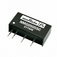
CONV DC/DC 2W 5VIN 5VOUT SIP

NMG0505SC

Manufacturer Part Number
NMG0505SC
Description
CONV DC/DC 2W 5VIN 5VOUT SIP
Manufacturer
Murata Power Solutions Inc
Series
NMGr
Type
Isolatedr
Datasheet

Specifications of NMG0505SC

Output
5V
Number Of Outputs
1
Power (watts)
2W
Mounting Type
Through Hole
Voltage - Input
4.5 ~ 5.5V
Package / Case
7-SIP Module (4 Leads)
1st Output
5 VDC @ 400mA
Size / Dimension
0.77" L x 0.30" W x 0.40" H (19.6mm x 7.6mm x 10.2mm)
Power (watts) - Rated
2W
Operating Temperature
-40°C ~ 85°C
Efficiency
83%
Approvals
UL
Dc / Dc Converter O/p Type
Fixed
No. Of Outputs
1
Input Voltage
4.5V To 5.5V
Power Rating
2W
Output Voltage
5V
Output Current
400mA
Supply Voltage
5V
Dc / Dc Converter Case Style
SIP
Product
Isolated
Output Power
2 W
Input Voltage Range
4.5 V to 5.5 V
Input Voltage (nominal)
5 V
Output Voltage (channel 1)
5 V
Output Current (channel 1)
400 mA
Isolation Voltage
1 KV
Lead Free Status / RoHS Status
Lead free / RoHS Compliant
3rd Output
-
2nd Output
-
4th Output
-
Lead Free Status / Rohs Status
 Details
Other names
811-1702-5

Available stocks

Company
Part Number
Manufacturer
Quantity
Price
Part Number:
NMG0505SC
Manufacturer:
Murata Power Solutions Inc
Quantity:
135
Company:
Part Number:
NMG0505SC
Quantity:
313
FEATURES
PRODUCT OVERVIEW
The NMG series of DC/DC Converters is
particularly suited to isolating and/or converting
DC power rails. The galvanic isolation allows the
device to be confi gured to provide an isolated
negative rail in systems where only positive rails
exist. The wide temperature range guarantees
startup from –40°C and full 2 watt output at 85°C.
Pin compatibility with the NMR series ensures
ease of upgradeability.
www.murata-ps.com
www.murata-ps.com
UL 60950 recognised
RoHS compliant
Effi ciency from 81%
Wide temperature performance at full
2 Watt load, –40°C to 85°C
UL 94V-0 package material
Industry standard pinout
1kVDC isolation
5V & 12V input
5V, 9V, 12V, & 15V output
Internal SMD construction
Fully encapsulated with toroidal
magnetics
No external components required
MTTF up to 3.9 million hours
Pin compatible with NMR series
No electrolytic or tantalum capacitors
www.murata-ps.com/rohs
For full details go to
 
1. See Ripple & Noise characterisation method.
2. Calculated using MIL-HDBK-217F FN2 with nominal input voltage at full load.
All specifi cations typical at T
SELECTION GUIDE
NMG0505SC
NMG0509SC
NMG0512SC
NMG0515SC
NMG1205SC
NMG1209SC
NMG1212SC
NMG1215SC
When operated with additional external load capacitance the rise time of the input voltage will determine the maximum external
capacitance value for guaranteed start up. The slower the rise time of the input voltage the greater the maximum value of the
additional external capacitance for reliable start up.
INPUT CHARACTERISTICS
Parameter
Voltage range
Refl ected ripple current
ABSOLUTE MAXIMUM RATINGS
Lead temperature 1.5mm from case for 10 seconds
Internal power dissipation
Input voltage V
Input voltage V
OUTPUT CHARACTERISTICS
Parameter
Rated Power
Voltage Set Point Accuracy
Line regulation
ISOLATION CHARACTERISTICS
Parameter
Isolation test voltage
Resistance
GENERAL CHARACTERISTICS
Parameter
Switching frequency
TEMPERATURE CHARACTERISTICS
Parameter
Specifi cation
Storage
Case Temperature above
ambient
Cooling
Order Code
IN
IN,
, NMG05 types
NMG12 types
A
12
12
12
12
=25°C, nominal input voltage and rated output current unless otherwise specifi ed.
V
5
5
5
5
Conditions
Continuous operation, 5V input types
Continuous operation, 12V input types
Conditions
T
See tolerance envelope
High V
Conditions
Flash tested for 1 second
Viso= 1000VDC
Conditions
Conditions
All output types
NMG0505
NMG1205
All other output types
Free air convection
A
12
15
12
15
=-40
V
5
9
5
9
IN
°C
to low V
Technical enquiries email: mk@murata-ps.com, tel: +44 (0)1908 615232
400
222
167
133
400
222
167
133
mA
to 85
°C
IN
Isolated 2W Single Output DC/DC Converters
470
455
450
450
200
190
190
185
mA
5.7
4.2
3.8
3.4
4.2
2.6
2.4
2.0
%
7.3
5.9
5.1
4.5
4.9
3.1
2.9
2.4
28
20
18
16
22
16
13
12
mVp-p
2010/02/12 KDC_NMG.C01 Page 1 of 5
1000
Min.
10.8
Min.
Min.
Min.
Min.
4.5
-40
-50
10
35
25
25
25
35
25
25
25
300°C
550mW
7V
15V
NMG Series
81
84
84
84
81
83
85
85
%
Typ.
Typ.
1.05
Typ.
Typ.
Typ.
7.5
12
60
5
86.5
87.5
87.5
83.5
83
87
88
88
%
Max.
Max.
Max.
Max.
Max.
13.2
125
5.5
1.2
15
85
30
25
20
2
pF
33
40
40
40
40
61
74
68
mA p-p
Units
Units
Units
Units
Units
%/%
VDC
kHz
3956
3682
3299
2833
2519
2405
2235
2011
kHrs
°C
W
V

Related parts for NMG0505SC

NMG0505SC Summary of contents

Page 1

... Pin compatibility with the NMR series ensures ease of upgradeability.   For full details go to www.murata-ps.com/rohs www.murata-ps.com Isolated 2W Single Output DC/DC Converters SELECTION GUIDE Order Code NMG0505SC 5 5 400 470 NMG0509SC 5 9 222 455 NMG0512SC 5 12 167 ...

Page 2

TEMPERATURE DERATING GRAPH Safe Operating Area 0 - Ambient Temperature (°C) TECHNICAL NOTES ISOLATION VOLTAGE ‘Hi Pot Test’, ‘Flash Tested’, ‘Withstand Voltage’, ‘Proof Voltage’, ‘Dielectric Withstand Voltage’ & ‘Isolation Test Voltage’ are all terms that ...

Page 3

... Typical start up times for this series, with a typical input voltage rise time of 2.2μs and output capacitance of 10μF, are shown in the table below. The product series will start into a capacitance of 47μF with an increased start time, however, the maximum recommended output capacitance is 10μF. Start-up time NMG0505SC NMG0509SC NMG0512SC ...

Page 4

... Inductor: The rated current of the inductor should not be less than that of the output of the DC/DC converter. At the rated current, the DC resistance of the inductor should be such that the voltage drop across the inductor is <2% of the rated voltage of the DC/DC converter. The SRF (Self Resonant Frequency) should be >20MHz. Inductor L, μH NMG0505SC 10 82103C NMG0509SC 22 ...

Page 5

... PACKAGE SPECIFICATIONS MECHANICAL DIMENSIONS 0.774 (19.65) (Max.) 0.301 (7.65) (Max.) NMG0505SC 0.4 XYYWWi (10.15) (Max 0.181 (4.60) 0.142 (3.60) 0.1 (2.54) 0.099 (2.52) 0.061 (1.54) 0.057 (1.45) 0.5 (12.70) 0.039 (1.00) All dimensions in inches ±0.01 (mm ±0.25mm). All pins on a 0.1 (2.54) pitch and within ± ...

Related keywords