UCH-3.3/30-D48NB-C Murata Power Solutions Inc, UCH-3.3/30-D48NB-C Datasheet
UCH-3.3/30-D48NB-C
Specifications of UCH-3.3/30-D48NB-C


Related parts for UCH-3.3/30-D48NB-C


UCH-3.3/30-D48NB-C Summary of contents
Page 1
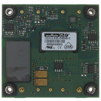
... UCH’s proven SMT-on-pcb designs. An optional baseplate offers full output power at maximum temperature. UCH’s feature input fi lters, input undervoltage and overvoltage lockout, output current limiting, short-circuit protection, and thermal shutdown. Additionally, all devices have output trim capability and an on/off control pin that can be ordered with either polarity ...
Page 2
Please refer to the full ...
Page 3
... M3 x 0.50 threaded insert and standoff (4 places) Screw length must 2.40 not go through Baseplate (60.96) UCH with Optional Baseplate B Do not remove M3 x 0.50 threaded inserts from bottom PCB 0.015 minimum clearance between standoffs and highest component 2.00 2 ...
Page 4
Performance Specifi cations and Ordering Guide ➀ Input voltage range Start-up threshold, Volts 34 Undervoltage 32 shutdown, V Overvoltage shutdown Refl ected (back) ripple cur- 10 rent, mA pk-pk Full load conditions 2 Inrush transient, A sec Output short circuit, ...
Page 5
Input voltage range Start-up threshold, Volts 34 Undervoltage 33 shutdown, V Overvoltage shutdown Refl ected (back) ripple cur- 15 rent, mA pk-pk Full load conditions 2 Inrush transient, A sec Output short circuit, mA Low line (V = min.), Amps ...
Page 6
Input to Output, Volts min. Input to baseplate, Volts min. Baseplate to output, Volts min. Isolation resistance, MΩ Isolation capacitance, pF Isolation safety rating Current limit inception (98 max after warmup), Amps OUT Short circuit protection ...
Page 7
Input to Output, Volts min. Input to baseplate, Volts min. Baseplate to output, Volts min. Isolation resistance, MΩ Isolation capacitance, pF Isolation safety rating Current limit inception (98 OUT after warmup), Amps Short circuit protection method Short ...
Page 8
Outline dimensions Baseplate material Pin material Pin diameter Weight, ounces 1.68 Weight, grams 47 Electromagnetic interference (conducted and radiated) (external fi lter required) Flammability Safety D24 Models - Volts, max. continuous Volts, transient, 100 mSec D48 Models - Volts, max. ...
Page 9
... Output noise may be further reduced by adding an external fi lter. Logic circuits with low power voltages may have a small voltage margin between logic ZERO and logic ONE, requiring noise sup- pression. Use only as much output fi ltering as needed to achieve your noise requirements. Excessive output capacitance can retard transient response or possibly cause instability. Low ESR ceramic capacitors may degrade dynamic performance ...
Page 10
... Users should be aware however of input sources near the Under-Voltage Shutdown whose voltage decays as input current is consumed (such as ca- pacitor inputs), the converter shuts off and then restarts as the external capaci- tor recharges. Such situations could oscillate. To prevent this, make sure the operating input voltage is well above the UV Shutdown voltage AT ALL TIMES ...
Page 11
... LOAD 2-3 INCHES (51-76mm) FROM MODULE Since these are isolated DC/DC converters, their outputs are “fl oating” with respect to their input. The essential feature of such isolation is ideal ZERO CURRENT FLOW between input and output. Real-world converters however do exhibit tiny leakage currents between input and output (see Specifi cations). ...
Page 12
... The remote Sense lines carry very little current. They are also capacitively coupled to the output lines and therefore are in the feedback control loop to regulate and stabilize the output. As such, they are not low impedance inputs and must be treated with care in PC board layouts. Sense lines on the PCB should run adjacent to DC signals, preferably Ground ...
Page 13
Connect trim resistor between Connect trim resistor between trim pin and −Sense trim pin and +Sense 1 R (kΩ) = − (kΩ) = TrimUp TrimDn ' ' − V NOMINAL OUT V NOMINAL V is ...
Page 14
... Please contact MPS for details this date, the following products are available: UCH-3.3/30-D48NBHL2-Y UCH-5/10-D48NBHL2-Y UCH-3.3/15-D48NBHL2-Y UCH-3.3/35-D24NBHL2-Y These are all negative On/Off polarity, baseplate installed, conformal coating added, 3.68mm pin length, and RoHS-5 hazardous substance compliance (with lead). www.murata-ps.com Isolated, “ ...
Page 15
... UCH-3.3/10-D24 Efficiency and Power Dissipation vs Line Voltage and Load Current @25˚ Load Current (Amps) UCH-1.8/40-D48 Maximum Current Temperature Derating 45 12 9.9 8.8 35 7.7 30 6.6 5.5 25 4.4 3.3 20 2 UCH-2.5/40-D48 Maximum Current Temperature Derating UCH-3.3/10-D48 Maximum Current Temperature Derating vs Line Voltage and Load Current @25˚ ...
Page 16
... Load Current (Amps) UCH-3.3/30-D48 Efficiency and Power Dissipation vs Line Voltage and Load Current @25˚ Load Current (Amps UCH-3.3/35-D24 Maximum Current Temperature Derating UCH-3.3/30-D48 Maximum Current Temperature Derating www.murata-ps.com Isolated, “Half-Brick” 1.8−15V Output DC/DC Converters Ambient Temperature ( ° Ambient Temperature ( ° Page ...
Page 17
... Load Current (Amps) UCH-5/20-D24 Maximum Current Temperature Derating UCH-5/30-D48 Maximum Current Temperature Derating UCH-12/4.2-D48 Maximum Current Temperature Derating at sea level 2.94 3.36 3.78 4.2 30 www.murata-ps.com Isolated, “Half-Brick” 1.8−15V Output DC/DC Converters Ambient Temperature ( ° Ambient Temperature ( ° C) ...
Page 18
... ISO 9001 and 14001 REGISTERED UCH-12/12.5-D48 Maximum Current Temperature Derating 12 11.5 16 19 8 UCH-15/6.7-D48 Maximum Current Temperature Derating 4.5 5 5.5 6 6.5 30 Murata Power Solutions, Inc. makes no representation that the use of its products in the circuits described herein, or the use of other technical information contained herein, will not infringe upon existing or future patent rights. The descriptions contained herein do not imply the granting of licenses to make, use, or sell equipment constructed in accordance therewith. Specifi ...