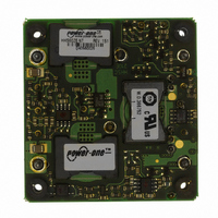
HHS60ZE-NT POWER ONE, HHS60ZE-NT Datasheet - Page 8

HHS60ZE-NT
Manufacturer Part Number
HHS60ZE-NT
Description
CONV DC-DC 48V IN 3.3V OUT 198W
Manufacturer
POWER ONE
Series
HHSr
Type
Isolatedr
Datasheet
1.HHS60ZD-NT.pdf
(12 pages)
Specifications of HHS60ZE-NT
Output
3.3V
Number Of Outputs
1
Power (watts)
198W
Mounting Type
Through Hole
Voltage - Input
36 ~ 75V
Package / Case
9-DIP Module, 1/2 Brick
1st Output
3.3 VDC @ 60A
Size / Dimension
2.40" L x 2.28" W x 0.50" H (61mm x 57.9mm x 12.7mm)
Power (watts) - Rated
198W
Operating Temperature
-40°C ~ 110°C
Efficiency
90%
Approvals
CSA, cUL, TUV, UL
Lead Free Status / RoHS Status
Contains lead / RoHS non-compliant
3rd Output
-
2nd Output
-
4th Output
-
Other names
179-2245
Available stocks
Company
Part Number
Manufacturer
Quantity
Price
Company:
Part Number:
HHS60ZE-NT
Manufacturer:
EUPEC/Infineon
Quantity:
1 000
Part Number:
HHS60ZE-NTS2
Manufacturer:
POWER
Quantity:
20 000
Short Circuit Operation
Figure 13. Output Current with Shorted Output Pins,
Vin = 48Vdc, Scale is 20Amp/Div.
Once the output current is brought back into its
specified range, the converter automatically exits the
hiccup mode and continues normal operation.
Overvoltage Protection
The output overvoltage protection consists of a
separate control loop, independent of the primary
control loop. This control loop has a higher voltage
set point than the primary loop. In a fault condition
the converter limits its output voltage and latches off.
Figure 14 shows operation of the converter under an
overvoltage condition.
JUN 06, 2006 revised to JUL 25, 2006
Figure 14. Output Voltage of an HHS60ZE Under a Forced
Overvoltage Condition, Vin=75V, Min Load, Co=none
48VDC Input, 60 Amp Half-Brick Converter
Page 8 of 12
Typical Application
Figure 15 shows the recommended connections for
the HHS60 Series converter.
The HHS60 Series converters do not require any
external components for proper operation. However,
if the distribution of the input voltage to the converter
contains significant inductance, the capacitor C1
may be required to enhance performance of the
converter.
capacitor with the ESR < 0.7Ω is recommended for
the HHS60 series.
If the magnitude of the inrush current needs to be
limited, for suggestions see the “Inrush Current
Control Application Note” on the Power-One website
at www.power-one.com.
For output decoupling we recommend using one
10μF tantalum and one 1μF ceramic capacitors
connected directly across the output pins of the
converter. Note, that the capacitors do not substitute
the filtering required by the load.
Shutdown Feature Description
The ON/OFF (# 3) pin of the HHS60 Series
converters is referenced to the –Vin (# 1) pin (see
Figure 5). Both negative and positive logic models
are available.
With negative logic (which is denoted by the suffix “–
N” in the part number), when the ON/OFF pin is
pulled low, the unit is turned on.
With the positive logic, when the ON/OFF pin is
pulled low, the output is turned off and the unit goes
into a very low input power mode.
HHS60 DC-DC Series Data Sheet
Figure 15. Typical Application of the HHS60 Series
Fuse
C1
A minimum of a 100 μF electrolytic
On/Off
+Vi
-Vi
HHS60ZX
+Sense
-Sense
Trim
+Vo
-Vo
www.power-one.com
C2
C3


